This topic is to discuss the following lesson:
Only one comment:
-Second scenary: BPDUs between SW2 and SW4: “Since SW2 temporarily claimed itself as the root bridge”, it should say “Since SW3 temporarily claimed itself as the root bridge”. Let me get to knoe im a mistake, thanks.
rEgards
Jose
Hello Jose
Yes as far as I can see you are correct. I will let @ReneMolenaar know to change it.
Thanks!
Laz
Hi guys,
two questions:
-
When the root bridge looses a connection like in the example shown, why does it not send a TCN?
Why only a TC trap is generated? It lost one of its designated ports. Or is that not a topology change from the roots perspective? -
When a new root port is elected on a switch and the new root port is the former designated port, there is now listening/learning/forwarding process happening, right? Because the port did that already and is already in a “forwarding” state!? Only if a port is in blocking state or the port just came UP, correct?
Thanks!
Hello Florian
Question 1
The Root bridge never sends out TCNs because a TCN is used primarily to inform the root bridge of the topology change. More accurately, it is used to inform all switches between the topology change and the root bridge of the change. If a topology change occurs on the actual root bridge, it doesn’t need to send a TCN based on the above description. Note the following Cisco documentation:
Question 2
When a port changes from Designated port (forwarding state) to root port (also forwarding state) it doesn’t have to go through the process of listening/learning/forwarding. It is already in the forwarding state and it remains so until it goes down and is brought back up or until it receives superior BPDU due to a topology change.
I hope this has been helpful!
Laz
3 Likes
Hi Laz,
thanks a lot for your answer!
-
I thought it might be faster for the root bridge to send a BPDU with the TC bit set right away when it realizes that a link is down, instead of waiting to hear from other switches in the network through a TCN and then sending the BPDU with the TC set.
-
Got it
I have two more questions.
-
Just read the “Spanning-Tree UplinkFast” article and at one point the ND port changes to become the new root port, but it only goes through listening/learning/forwarding. I thought a ND equals a blocking port and thus needs to wait 20sec before starting the listening/learning/forwarding process!?
-
The last part describes that even though the old root port is active again the switch does not change to that port right away. Why not? Is that a behavior caused by Uplinkfast or is it normal?
Because the best BPDU is received on that port so why does it not change?
Does it have to do that the port on SW1 needs 50sec to become active?
Thanks a lot for your help!
Hello Florian
Concerning Question 1, if a root bridge learns about a topology change that is due to the change of state of its own interfaces, then it will immediately know of the topology change, so it does not actually have to “wait” to be informed by other switches. Once again, the TCN is sent to inform all the switches between the location where the topology change took place and the root bridge of the TC.
Question 3:
Yes you are correct that the ND port is indeed blocking. However, because its initial state is blocking, this state is not explicitly expressed in the debug output shown in the lesson. The debug output for blocking will only appear when the blocking state began, that is, when the port transitioned to the blocking state from whatever other state it was in. In the example in the lesson, the debug shows the change from blocking to listening, listening to learning, and learning to forwarding.
Question 4:
When the old root port is active again and uplinkfast is enabled, the behaviour of STP will be the following:
- Once the old root port is enabled, it receives superior BPDUs immediately
- The root port delay timer will kick in which is typically 35 seconds in which it remains in the listening state. It never actually goes into the learning state before entering the forwarding state
- The result is that the root port does not switch back immediately, but takes a delay to go back.
This is indeed a result of the configuration of the uplinkfast feature on the switch. If it switches back immediately, the Fa0/14 port will become the root port, but the corresponding port on the root switch will still take the typical amount of time to go through all of the STP states to become forwarding as well. So this avoids a temporary loss of connectivity.
For reference for the questions above, the link to the UplinkFast lesson is included below.
I hope this has been helpful!
Laz
Hi according to the result for the overview with the new port state and the diagram at the end . The Diagram and the " SW1#show spanning-tree | begin Interface " dont match .
Sw1 Gi0/2 Desg FWD 4 (on diagram doesnt even exist the interface its shut )
Hello Florin
Thanks for pointing that out, I will let Rene know to fix the typo.
Thanks again!
Laz
Hello Florin,
Do you mean this one?
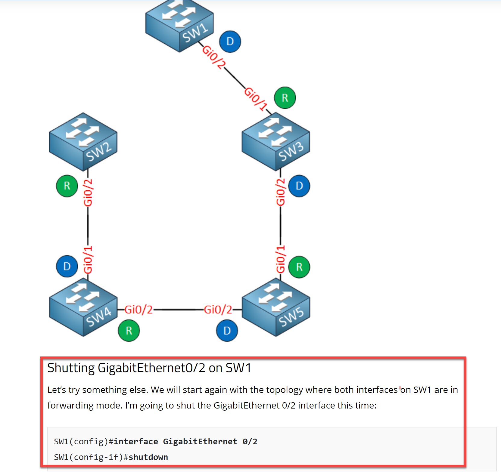
I didn’t add a new topology picture with all interfaces up for this example. Maybe I should, it could be confusing like this. I only mention in the text that we start with a topology with two active interfaces on SW1.
Rene
Diagram for the last Logical Topology is not represented correctly by the outputs in the CLI. for instance SW5 Shows two different DES/RP information that doesn’t reflect in the Last Logical Topology you display. I believe the ports and their associated roles are mixed up. Gi0/1 shows itself as a Root port on SW5 on the CLI output but shoes it as a DES on the logical topology… that confused me…
Hi,
I would like to ask is TCN only sent on Root Port toward Root Bridge? Because I saw somewhere mentioned TCN can also be sent from designated port if Root Port failed. Need some clarification. Thank you.
Hello Kwok
A TCN will only be sent out of a root port towards the root bridge. If the root port fails, then STP will try to reconverge and determine a new port on the switch to choose as a root port. A switch will always have a root port to send out TCNs unless it becomes the root bridge. Then it won’t have a root port, but as a root bridge, it will never send out TCNs.
So only a root port will send out TCNs, never a designated port. The following Cisco documentation also helps to clarify this:
I hope this has been helpful!
Laz
Hi All,
regarding section 2.1 “Shutting GigabitEthernet0/1 on SW1” of this lesson,
I have some difficulties in understanding the timing of the changes on SW2/SW4:
how is it possible that SW2 converges before SW4, if SW2 is triggered by the Superior BPDU provided by SW4?
SW2#
02:51:09: STP: VLAN0001 heard root 32769-fa16.3e5d.b4a0 on Gi0/2
02:51:09: STP: VLAN0001 Topology Change rcvd on Gi0/2
02:51:09: STP: VLAN0001 sent Topology Change Notice on Gi0/1
02:51:10: STP: VLAN0001 heard root 32769-fa16.3e5d.b4a0 on Gi0/2
02:51:10:     supersedes 32769-fa16.3e95.a9c9
02:51:10: STP: VLAN0001 new root is 32769, fa16.3e5d.b4a0 on port Gi0/2, cost 4
02:51:10: STP: VLAN0001 sent Topology Change Notice on Gi0/2
**02:51:11: STP: VLAN0001 heard root     1-fa16.3eca.4096 on Gi0/2**
**02:51:11:     supersedes 32769-fa16.3e5d.b4a0**
02:51:11: STP: VLAN0001 new root is 1, fa16.3eca.4096 on port Gi0/2, cost 16
SW4#
02:51:16: STP: VLAN0001 heard root     1-fa16.3eca.4096 on Gi0/1
02:51:16:     supersedes 32769-fa16.3e5d.b4a0
**02:51:16: STP: VLAN0001 new root is 1, fa16.3eca.4096 on port Gi0/1, cost 8**
**02:51:16: STP: VLAN0001 sent Topology Change Notice on Gi0/1**
02:51:17: STP: VLAN0001 Topology Change rcvd on Gi0/1
02:51:17: STP: VLAN0001 heard root     1-fa16.3eca.4096 on Gi0/2
02:51:17:     supersedes 32769-fa16.3e5d.b4a0
02:51:17: STP: VLAN0001 new root is 1, fa16.3eca.4096 on port Gi0/2, cost 12
02:51:17: STP: VLAN0001 sent Topology Change Notice on Gi0/2
thanks
1 Like
Hello Giacomo
Yes indeed, it seems that SW2 becomes aware of the root bridge via Gi0/2 before SW4 based on the timestamps we see in the output. However, it may be that there is a slight synchronization problem between the clocks on the switches. I’ll let Rene know to take a look and make any necessary corrections…
I hope this has been helpful!
Laz
Hi @giacomo.monari,
You have a good eye. I think SW4 was off by about 5 seconds. It’s been a while since I labbed this and I think I used VIRL. It’s possible that the clocks weren’t synced 100%. I fixed this ![]()
Rene
1 Like
I didn’t understand why cost for interfaces of SW1 was 4 after reconvergency. Since SW1 is still root bridge after reconvergency, so the cost for interfaces must be 0.
Hello Sahil
When issuing the show spanning-tree command, the cost shown in the table for each port is not the cost to reach the root bridge, but the cost that that particular port adds to any path to the root bridge. You will see that the cost is 4 for all interfaces on all switches. This is based on the cost that is assigned to GigabitEthernet ports, which is 4.
The total cost to the root bridge in this lesson can be seen in the debugs of the switches, and is contained within the BPDUs that reach those switches. You can also see the total cost to the root bridge by issuing the following command:
Now in the lesson, Rene used the | begin Interface pipe command to remove any additional information, and just to show the table of all switch ports. If he didn’t do that, you would see something similar to the following:
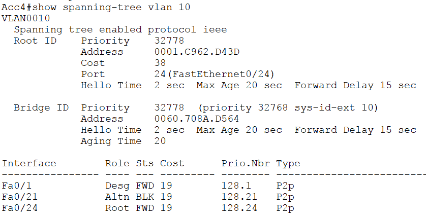
This output is from another topology. Here you can see that for VLAN 10, the cost is 38. That is the cost from the local bridge to the root bridge. But the cost of each port is also shown in the table. Remember the cost in the table is the cost that that particular port would add to the total cost to the root bridge. These are Fa ports, which have a default cost of 19.
For more information about cost in an STP topology, take a look at this lesson:
I hope this has been helpful!
Laz
1 Like
When the TC is detected by the Root Bridge (local link down) it will delivery a TC BPDU (TC flag bit in 1) downstream to the non roots ?
An when a TC is detected by a Non Root Bridge, first it sends a TCN BPUD to upstream Non Root Bridge, then this ack the TCN with a TCA , and repeat this steps until reach the Root Bridge that has to do the TC BPDU flag bit in 1 downstream to the non root bridges ?
Hello Juan
Take a look at this NetworkLessons Note on the STP topology change process.
I hope this has been helpful!
Laz
1 Like