Hi Laz,
Thanks for your answer. I don’t use SPAN but direct observation through GNS3.
I always think that I work on real devices !!! I’ll remember about those simulators limitations next time !!!
Thanks for pointing me that out .
Regards
1 Like
First of all really appreciate for such a wonderful explanation .
I wan to know If we are receiving BPDU on same switch from more than one port So in this case blocking will not take 20s to move to listening and learning ?
If switch only receive from one direction than in that case only It requires 20s from blocking to listening and learning .
Thanks
Hello Osama
It is possible to have the same BPDU arrive on more than one port of the same switch. First of all, this lesson and the related configurations are all using classic STP 802.1D. This means that all BPDUs are generated by the root bridge, and are propagated down the tree. If there is a physical Layer 2 loop, then one switch can receive BPDUs from multiple ports.
Of course, each BPDU will have a specific cost value in the header, and whichever BPDU has the lower cost, it will become the root port. Take a look at the following lesson for details about this process.
Remember that BPDUs may still be received on blocked ports, but if they are not superior, they are simply ignored.
I hope this has been helpful!
Laz
if the situation changed to that the link between SW1 & SW2 is the one that goes down and still we have connectivity between SW1 & SW3 , will it take still 30 seconds for STP to re-converge or 50 seconds ?
Hello Mohamed
Whenever there is a topology change (a link goes down) on a switch other than the local switch, (an indirect link failure) then in such a situation, STP will reconverge in 50 seconds. This is due to the addition of the blocking timer, which is 20 seconds. Take a look at this post which refers to the blocking timer:
For a more comprehensive view of the reconvergence of STP, take a look at the following lesson:
I hope this has been helpful!
Laz
1 Like
Hello, everyone.
About uplinkfast. From what I know, the listening/learning states are used to ensure that the device can adapt to the STP topology and not create any loops, correct?
However, with uplinkfast, you can immediately make a blocking port a forwarding port in case you lose your root port. However, this means that you skip learning and listening. So doesn’t this create the potential for a loop to occur?
Or is it correct to say that the device already knows the current STP topology is loop-free since it already calculated it before. Or in other words, you can transition a port from blocking to forwarding because you know it won’t form a loop since you already went through the process once before.
David
Hello David
In normal STP operation, a switch port goes through listening and learning states to avoid creating loops, as you mentioned. However, UplinkFast is a Cisco-specific optimization designed for quick recovery in case of a direct link failure. It’s typically used in access-layer switches that have redundant links to the distribution layer.
When UplinkFast is enabled, a switch keeps track of alternate paths to the root bridge. If the primary path fails, the switch already knows about an alternate path and can transition the blocking port to forwarding almost immediately, skipping the listening/learning states.
This doesn’t create a loop because UplinkFast also modifies the BPDUs that the switch sends out. The switch makes its other ports appear less attractive to downstream switches by artificially increasing the path cost in the BPDUs. This prevents downstream switches from choosing the recovering switch as their new path to the root bridge, avoiding potential loops.
Even so, UplinkFast should be deployed carefully. Ideally, it should only be applied on access layer switches and not on distribution or core layer switches.
I hope this has been helpful!
Laz
Hello Team,
It was comprehensive until I got to the final statement. So what’s the point of having uplinkfast if there is still a delay in convergence time? If you could shed some light on this, that would be great.
Hi Team,
-
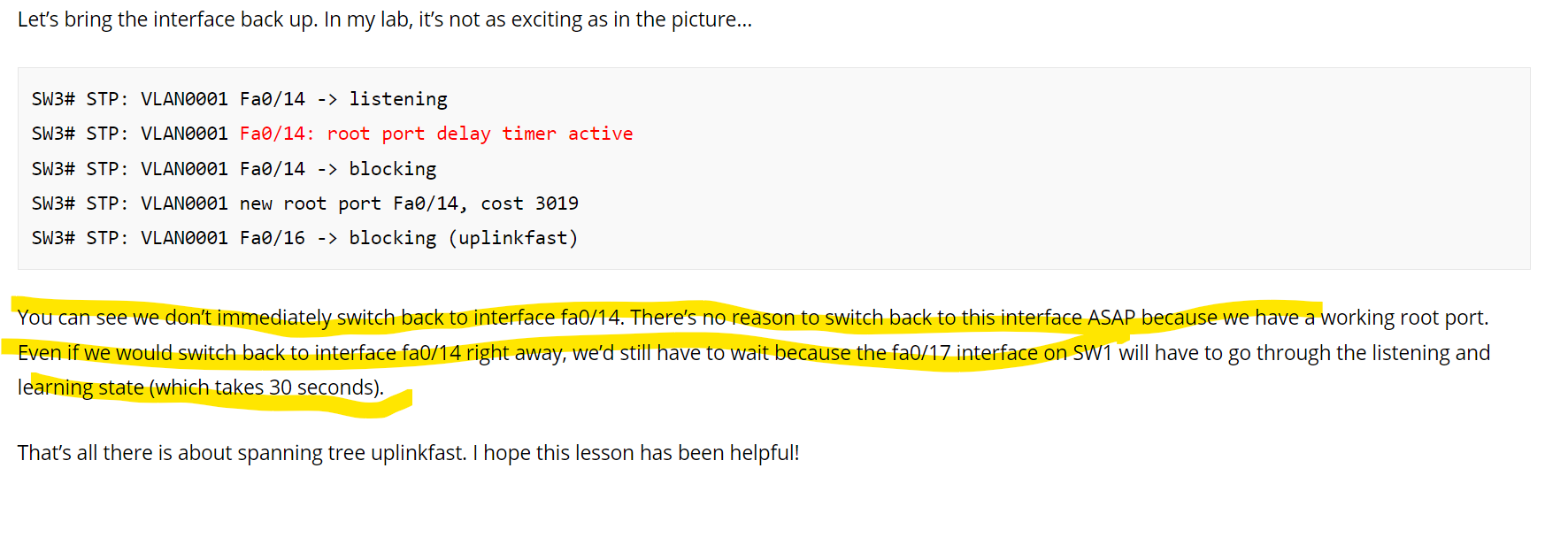
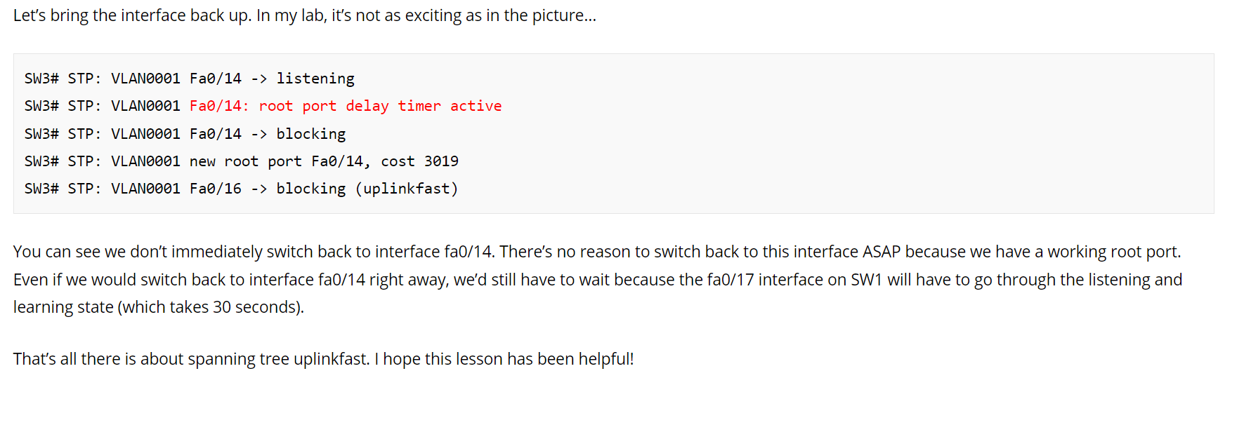
I did this in lab , it immediately turned up and moved to Root state(FWD) in 2secs. As you stated that it takes time since there is working root port. but in my lab it was not so.
-
Why has the bridge priority increased to 49152 and the interface cost to 3100 for the bridge that has uplinkfast enabled?.
-
What would be the convergence time for selecting root bridge? .The reason i am asking this is as i did couple of tests in LAB where i dont see the constructive convergence time for selecting root bridge. I did play around the root ID on different switches but the time seems not same for all. So confused on this. Please clarify on this
Hello Sathish
I understand the confusion. If you look at the initial link failure between SW1 and SW3, you can see that on SW3 the port that failed was a root port!! Because SW3 no longer had a root port, it needed to reconvervge quickly to reestablish connectivity and return to a state of stability.
Now when the link came back up, SW3 already had a root port, and the STP topology was already stable, so there was no need to quickly change states. That’s why there is a delay, because the topology is already stable, and the delay will not affect connectivity or the forwarding of traffic.
This delay is important because it ensures that if a port is flapping, the STP topology won’t also flap. Imagine the link between SW1 and SW3 continues to go up and down (flapping). If there was no root port delay timer, the STP topology would continually try to reconverge, resulting in instability. The delay however results in Fa0/16 on SW3 remaining the root port during flapping, and traffic would be forwarded without any problems. Does that make sense?
I hope this has been helpful!
Laz
This is the behavior of Uplinkfast. This is done in order to prevent the local switch from becoming the root and to be used as a transit to the root.
The uplinkfast feature is supposed to be used in leaf/node switches.
1 Like
Hello Sathish
Strictly speaking, Uplinkfast will employ the root port delay timer whenever the original root port that failed comes back up. That delay timer according to Cisco is 50 seconds and is not configurable.
However, there could be several reasons for the behavior you are seeing.
- UplinkFast is not part of the original STP design, it is a Cisco enhancement designed to improve convergence, so its implementation may vary from platform to platform.
- The behavior described in the lesson is for the original 802.1D standard. Using a different type of STP may affect the behavior of uplinkfast.
- For example, if the default STP version on your device is RSTP, then the Uplinkfast configuration will have little effect because RSTP inherently reconverges quickly and ignores any uplinkfast configurations.
When you enable UplinkFast on a switch, it increases the bridge priority to 49152 to ensure that the switch won’t become the root bridge, since UplinkFast is designed for non-root switches. The interface cost is increased to 3100 to prevent the switch from becoming a designated switch on any of the connected segments.
The convergence time for selecting a root bridge can vary based on several factors, such as the number of switches in your network, the speed of your links, the current load on your network, and the specific STP enhancements you have enabled (like RSTP, UplinkFast, or BackboneFast). It’s normal to see some variability in convergence time during your lab tests. If you want to speed up the convergence time, you can consider enabling RSTP or tuning your STP timers.
I hope this has been helpful!
Laz
1 Like
Thanks @lagapidis for providing an excellent explanation.
Hi @ReneMolenaar ,
Once we restore the earlier root port (the link between SW1 & SW3), again, is it a Topology change? Does the Topology change mechanism to flush the MAC addresses and “dummy multicast frame” play a role here?
Thank You
Hello Mrigendra
This is an excellent question! No, the dummy multicast frames are not sent out again when the previously failed link is restored.
The dummy multicast frames are only sent as part of the UplinkFast mechanism when a redundant uplink (blocked port) transitions into the Forwarding state due to a primary uplink failure. Their role is to update the MAC address tables in upstream switches to ensure rapid convergence.
When the previously failed primary uplink comes back online, it does not immediately transition to the Forwarding state. Instead, STP runs its usual process. This controlled progression avoids any risk of temporary loops or incorrect forwarding behavior.
The reason for this is that there is no need for the dummy multicast frames to be sent out. Since the returning link does not disrupt the active forwarding path, because the redundant uplink is still in use, there is no need to send any dummy multicast frames. Once the port transitions back to Forwarding, upstream switches will naturally relearn MAC addresses based on normal unicast traffic. Does that make sense?
I hope this has been helpful!
Laz