Good lesson thanks Rene.
Rene/Laz - do you think we need to know vPC configuration for ENCOR or knowing the high level function is enough?
Good lesson thanks Rene.
Rene/Laz - do you think we need to know vPC configuration for ENCOR or knowing the high level function is enough?
Hello Bhawandeep
vPC is a feature of Cisco Nexus devices, and Cisco’s ENCOR certification doesn’t include Nexus devices. However, some similar features that you should be familiar with include:
I hope this has been helpful!
Laz
but on campus we use only IOS switches and not nexus so we cannot create vPC right ?
Hello Kapil
Yes, vPCs are a feature that is supported by Nexus series devices. However, it is possible to create a similar arrangement when using Cisco IOS devices. Such a feature is called Multichassis Etherchannel. There are various ways to implement this using IOS devices:
I hope this has been helpful!
Laz
Hello,
I have a question about the following statement:
“With the spine-leaf architecture, every end device is always a maximum of two hops away”
If Spine-Leaf is only used within a datacenter how is this different from the Three-tier design?
Does the traffic not flow the same way via acc-dist-acc and leaf-spine-leaf?
Thanks for a good lesson
Hello Dan
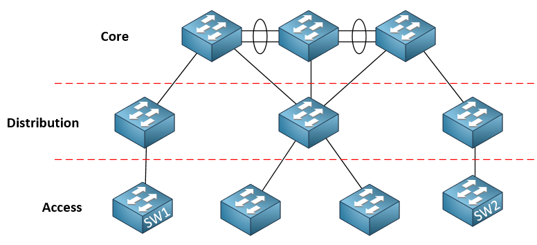
For smaller 3-tier networks, you typically have end devices (access switches) only two hops away, but this is not guaranteed. For an extensively large three-tier topology, you can easily have a distance between access switches exceed two hops. For example:
SW1 and SW2 are 6 hops away. Now that may be fine for an enterprise network where many of the access switches are in different buildings or could be in different cities, but for data centers, such a topology can be detrimental.
You can configure a 3-Tier network model in a data center to ensure that each access switch is at most two hops away from any other, but that would result in a collapsed core situation, where the distribution and core would become one.
In the following lesson Rene goes on to explain the communication between access switches in such a topology:
Conversely, the spine/leaf topology guarantees that any communication between two access switches is no more than 2 hops away. This is suitable, and preferable for data centers, but is not easily applied to enterprise networks, nor is it necessary to apply to enterprise networks, as data transmission patterns generally don’t require such connectivity.
I hope this has been helpful!
Laz
Hi Rene and Laz,
I have a question regarding the spine and leaf topology. If the spine are the core layer switches, does all spine switches also require to connect to each other? If the spine switches only connect to leaf switches, how does core switches communicate with each other in the spine area? Thank you!
Bruce
Hello Bruce
The short answer to your question is no, spine switches don’t need to be connected to each other. Actually, by definition, they should not be connected to each other. Spine switches should only be directly connected to leaf switches. Indeed, spine switches should not even have any uplinks either!
All servers and other network devices should be connected to leaf switches. Also, any uplinks to other parts of the datacenter or to more traditional networks should also take place via a special leaf switch called a border leaf.
This ensures that communication between any two entities on any two leaf switches will have only two physical links to traverse, and never more than two. This optimizes latency. If a data path went from spine to spine, you may have three or more such links to traverse.
The only things other than leaf switches that can be connected to a spine include the following:
Now having said that, I once again reiterate that there is no need for any communication between spine switches on the data plane. You can trace out multiple communication paths between any entities on any two leaf switches in such a topology without the need for inter-spine links. However, on the control plane, all of the spine switches must be connected to an APIC controller, in order to be managed.
I hope this has been helpful!
Laz
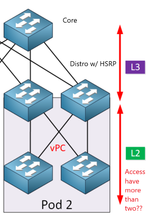
Simple question really, but want to verify my thinking. I have two Nexus switches acting as the distribution switches (they will have vlan SVI’s for inter-vlan routing) that are in a VPC domain. How many access switches can I connect to those Nexus switches? Also can I have L3 connections from Nexus to core switch or router? The drawing in the lesson is what I am basically doing. Since I cannot afford chassis switches and using VSS and can get 2 nexus switches I can create redundancy from my understating almost in the same way. The two Nexus SW could run HSRP or VRRP and the access layer switches see one switch but they are acting independently.
Thank you,
Alan
Hello Alan
Your thinking is correct. vPC is the Nexus methodology of creating redundancy between two Layer 3 switches. And yes, you can use HSRP/VRRP to employ layer 3 gateway redundancy for your access layer VLANs.
Now your question concerning how many access switches can you have in such a topology is a very good one. The only strict limitation here is the number of ports your Nexus switches have. If you have 24 ports on each switch for example, and four ports are being used for uplinks and your vPC connections, then the other 20 ports can all be used to connect to access switches. However, is that acceptable? Well it depends.
We must look here at the concept of oversubscription ratio. This is the ratio between the total downlink bandwidth and the total uplink bandwidth. For example, a distribution switch may have 48 1Gbps connected to access switches (downlinks), and one 10 Gbps port connected to the core layer (uplinks). The total aggregate bandwidth of the downlinks is 48 Gbps while the total aggregate uplink is 10 Gbps. The oversubscription ratio is 48:10 or 4.8:1.
This means that you are provisioning total downlink bandwidth at 4.8 times the total uplink bandwidth. This means that if all downlink connections were being used at full capacity at the same time, the uplink bandwidth would not be able to handle this traffic, and this is why the word “oversubscription” is used. However, this design depends upon the fact that this is a very rare occurrence, and in general, downlinks will never use full bandwidth all at the same time.
A general rule of thumb is that data oversubscription for access ports on the access to distribution uplink should not exceed 20:1 while from the distribution to the core links, this should not exceed 4:1.
So to answer your question, you can connect as many access switches as you like as long as your total aggregate uplink bandwidth to total aggregate downlink bandwidth is a ratio of 20:1 or less.
I hope this has been helpful!
Laz
Laz,
Thank you for the reply. But I hate to say that I am horribly confused now and not sure I have ever heard of this before. It does make sense though from a practical aspect that bandwidth needs to be large enough to handle all the traffic. If I have 8 access switches that are going to 150 host laptops at 1 Gbps each. Then from each access switches I am using two ports each running at 10 Gbps in ether channel for a total of 16 ports being used at the distro layer using VPC (that would be 8 connections per nexus switch). Then from Distro I have 2 ports at 10 Gbps ether channel going to the core how do I find out all these ratios you are talking about exactly? Sorry for the word salad here, basically all access ports are 1 Gbps where every other port is using 10 Gbps and ether channel.
Thank you,
Alan
Hello Alan
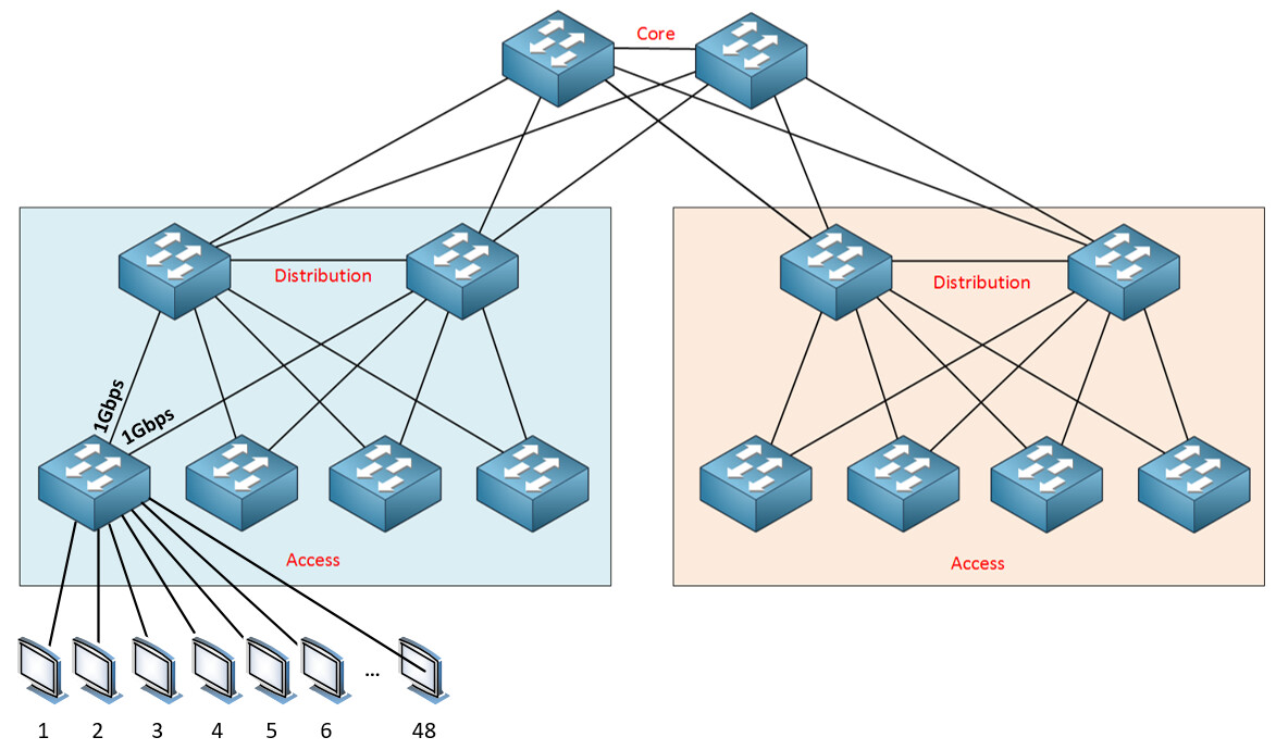
Sorry about the confusion. Let me try to clarify. When looking at a three-tier network design model, we have something like this:
Now, imagine that those computers at the bottom left each have a gigabit connection to that access switch. Now also imagine that there are 48 of those PCs connected to that access switch. Finally, imagine that the uplinks from that access switch are also 1Gbps speeds as shown.
Ideally, this should be less than 20:1.
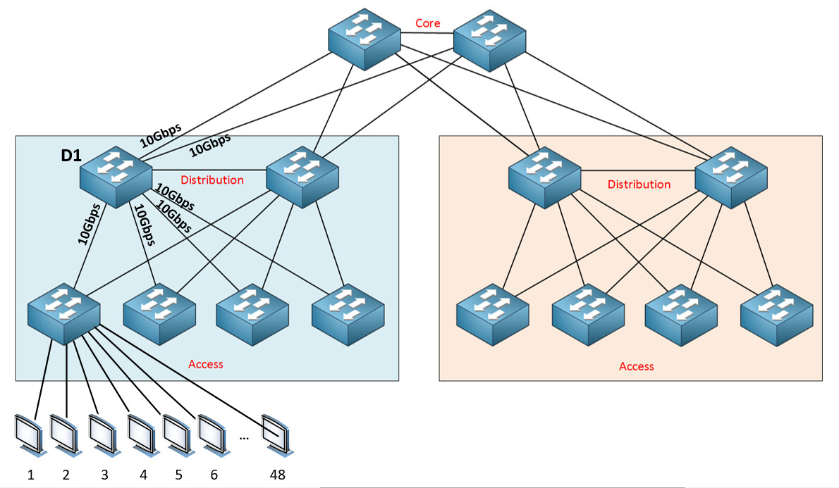
Now in a different scenario, take a look at the following diagram:
If you have a distribution switch such as the one labeled D1 in the diagram above, and you have four downlinks to the access layer, each of 10 Gbps, and two uplinks to the core layer, each at 10 Gbps, what is the oversubscription ratio?
This value is acceptable because the rule of thumb states it should be no larger than 4:1.
The oversubscription ratios are always calculated on a per switch basis, so you have to calculate them based on each individual switch. It’s simply the ratio of the aggregate downlink speed to the aggregate uplink speed.
This will tell you how many access switches you can connect to each distribution switch.
So each access switch has an aggregate downlink of 150 Gbps, and an aggregate uplink of 20 Gbps for an oversubscription ratio of 150:20 or 15:2 which is well below the 20:1 rule of thumb for the access layer.
For each distribution switch, you have 8 downlinks at 10 Gbps, and two uplinks at 10 Gbps. So the aggregate downlink speed is 80 Gbps, the aggregate uplink speed is at 20 Gbps, so your oversubscription ratio is 80:20 or 4:1 which is at the upper limit of the rule of thumb, so you’re OK.
I hope this has been helpful!
Laz
Laz,
As always thanks for dumbing this down with such a simple example that I can understand quickly (seriously). I cannot tell you how valuable you are to have around. With this info I was able to calculate everything I needed. Thanks for all the help you provide.
Alan
Hello Alan
Thanks for your kind words, it’s posts like yours that really make what we do worthwhile… It’s much appreciated.
Laz
Hello Laz,
In my case , we are using dell switches for traffic & 1 hw management switch for OOB traffic but in dell we’re using VLTi instead of STP configuration in switches.
So my query is in modern architecture, do we configure STP in cisco or juniper switches or VLTi is known by some other name in these vendors.
Hello Nitin
VLTi is a proprietary link aggregation protocol developed by Dell. It is the equivalent of EtherChannel for Cisco. So it’s not really a replacement for STP, but when you do employ it, like EtherChannel, STP is unnecessary, at least across the specific aggregated links.
In modern architecture, like in a spine and leaf topology similar to that in the lesson, STP is generally still used. If you employ something like VXLANs however, you eliminate the need for a loop prevention mechanism altogether because VXLANs by design, build a loop-free topology.
The following Cisco blog post is quite enlightening when it comes to alternatives to STP.
I hope this has been helpful!
Laz
Hi,
I just have a question somewhat related to this -
In my production we use cisco 4500’s in VSS pairs and cisco 9500’s in Stackwise virtual pairs.
I understand that with VPC (Nexus) and VLT (Dell) that both switches in the stack have different control planes etc. while with VSS and stackwise virtual there is just one control plane for both switches.
What I don’t understand is what are the advantages of VPC over VSS/Stackwise virtual ?
As an example I believe that if you want to route with VPC there are lots of extra steps involved so what exactly are the advantages of VPC and Dell VLT over VSS and stackwise virtual ?
Thanks.
Hello Sean
Indeed you are correct that VSS and stackwise both create a single control plane while vPC for nexus devices maintain a different control plane for each device. There is a good reason for this. By maintaining a separate control plane, vPC is more resiliant to failure. Remember that Nexus devices are specifically designed for datacenters, and require a higher level of availability.
In VSS and stackwise, the single control plane is a single point of failure. For example, in the event of a software update, a stack or a VSS pair must be rebooted. For access switches, or even for core switches, this can be done in a maintenance window with little or no impact to the network users. However, a datacenter must be up and running 24/7/365, so there is no convenient maintenance window.
A pair of vPC Nexus switches can have their NX-OS updated with zero downtime, because of the fact that they have different control planes. When one switch is being updated, the other takes over all activity, and visa versa.
So the advantage is that with individual control planes, the vPC nexus switches deliver a truly redundant high availability scenario, whereas stackwise and VSS don’t deliver that level of redundancy. Don’t get me wrong, stackwise and VSS are great because there is redundancy as far as power supplies, hardware, and redundant uplinks, which is more than enough for access, distribution, or even some core network components. But you need that little extra that vPC provides when you deal with datacenters.
On the other hand vPC can be more complex to configure especially when implementing routing as you say, or HSRP, or other features as well, but that’s part of the tradeoff of having the control planes of the devices remain independent.
I hope this has been helpful!
Laz
Dear Rene/lagapides, I would not question the quality on Networklessons, but having the topics listed as per exam would have been easier to check off, what we have learnt and what we know. and keeping the extra topics as bonus lessons would have made us understand them better. If this could be done, that would be awesome!!!
Hi i want to know how to configure the Spine and Leaf Architecture in lab i didnt see any lab regard Spine and Leaf Architecture in the site .
Regard
MBN