Spine and Leaf Architecture

Hello Mohamad

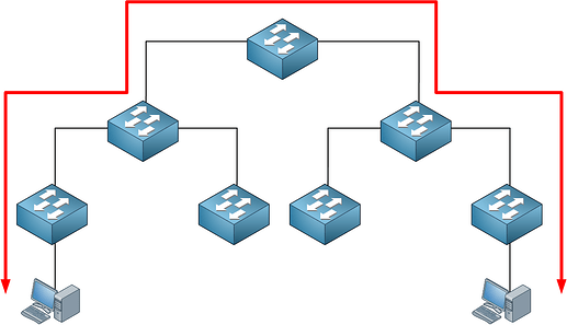
The spine and leaf architecture describes the way in which the switches are interconnected. It is primarily a physical layer architecture. The distinguishing feature, compared to the more traditional tiered model, is that every spine switch has a physical connection to every leaf switch. There is no specialized configuration on the devices to achieve this architecture.

Now having said that, there are some guidelines for configuration to keep in mind when implementing such an architecture, but these are not specific to the architecture itself but to general networking best practices.

  1. Don’t use STP. Ensure that your configuration does not rely on STP to prevent L2 loops, otherwise, you waste available bandwidth by causing all links but one to remain idle
  2. Configure VLANs only on leaf switches. Spine switches should remain unaware of VLAN configurations. Spine switches should perform routing between the VLANs configured on the leaves.
  3. Routing protocols configured to function with equal cost multipath should be implemented to ensure the most efficient usage of the multiple uplinks to the spine switches. For extensively large networks, Cisco recommends the use of BGP to ensure the scalability of such networks.

These are just a few of the best practices. You can find more information at the following Whitepaper, which has additional links and references.

I hope this has been helpful!

Laz
Hi,
When we have 2 nexus forming a vPC, in the show mac address-table, in column Ports, sometimes it is the port-channel number, sometimes it is vPC Peer-Link or even vPC Peer-Link(R). May I know the difference between the three please ? Thank you

Hello Amadou

On a Nexus device, when you issue the show mac address-table command, you may see something similar to this:

Legend:
* - primary entry, G - Gateway MAC, (R) - Routed MAC, O - Overlay MAC
age - seconds since last seen,+ - primary entry using vPC Peer-Link,
   (T) - True, (F) - False

VLAN     MAC Address      Type      age     Secure NTFY Ports/SWID.SSID.LID
----     -----------      ----      ---     ------ ---- -------------------
10       0000.0c9f.f002   dynamic   10      F      F    Po100
10       0000.0c9f.f003   dynamic   15      F      F    Po100 (R)
20       0000.0c9f.f004   dynamic   5       F      F    vPC Peer-Link
20       0000.0c9f.f005   dynamic   20      F      F    vPC Peer-Link (R)
30       0000.0c9f.f006   dynamic   0       F      F    Eth1/1
30       0000.0c9f.f007   dynamic   0       F      F    Eth1/2

Indeed in the Ports column, you may get a particular interface, a port channel, or a vPC link, and each one has a specific meaning.

Remember the MAC address table is used to correspond a MAC address with a particular interface or port on the switch. MAC addresses are learned when a frame enters a port. The source MAC address is recorded in the MAC address table, and the port on which it entered the switch is also recorded.

The Port column contains the port on which that particular MAC address was learned. Remember, Ethernet frames can enter a switch via a physical port, a port channel, or via the vPC peer link as well. Here are the various values you can see in the Ports column:

  • Physical interface - example: Eth1/2 - This MAC address was learned via a frame that entered the Ethernet 1/2 interface. This is a physical interface on the switch.
  • Port channel - example: Po100 - This MAC address was learned via a frame that entered port channel 100, which is a logical interface composed of multiple physical links.
  • vPC peer-link - The vPC Peer-Link is the special link between the Nexus switches that are part of the vPC domain. The MAC address was learned from the Peer-Link itself.
  • (R) - This indicates that the MAC address is associated with a routed port such as an SVI, a Layer 3 EtherChannel port, or a Layer 3 physical port.

Some more info about the show mac address-table on Nexus devices can be found here:

I hope this has been helpful!

Laz