In ospf to form neighborship why do we need the subnet mask to be same?
Also, why would mtu mismatch be an issue. Isn’t Ip will handle fragmentation?
Hello Tejas
The subnet mask is checked by OSPF only if a broadcast network type is being used, such as Ethernet. If it is a point to point connection, then no such check will take place. This is done so that the correct communication can take place between the two neighbors. If the network being shared between two OSPF neighbors have incorrect subnet masks, then when this network is being advertised by the two routers, it will be advertised with a different subnet mask. In other words, two different destinations would be advertised for the same network. This will cause other routers receiving this information to continually switch between the two resulting in a failure to converge.
Secondly, concerning the MTU mismatch, RFC 2328 which describes OSPFv2 states the following:
If the Interface MTU field in the Database Description packet indicates an IP datagram size that is larger than the router can accept on the receiving interface without fragmentation, the Database Description packet is rejected.
So if a router tries to negotiate an adjacency on an interface where the remote router has a different MTU, the adjacency will be denied. There are two reasons for this. The first is to eliminate any problems in the data plane, where user traffic is exchanged, where a sending host sends packets too large for a receiver (or a router along the path) to receive and process. The second and arguably more important for OSPF, is that it eliminates any problems in communication between OSPF routers in the control plane. Although fragmentation is an option, this is not preferred at all for any OSPF exchanges. Essentially, it keeps things as simple as possible as far as MTU goes so that failures will not occur due to MTU issues.
I hope this has been helpful!
Laz
So I have a question. I have two routers and a switch connected to each router. On the one switch OSPF neighbor shows all correct information with the correct neighbor ID going to my routers loopback address.
On the other switch, while I do form full adjacencies, the network ID is going to my 1 of my routers VLAN interface versus the routers loopback address. How can I fix this?
Thanks
Hello Jason
So from your description, you have two routers and two switches, and the switches are Layer 3 switches participating in OSPF. If I understood correctly, one of the switches is getting the correct Router ID from one of the routers, which is its neighbor, while the other switch is seeing an incorrect router ID from the other router, which is its OSPF neighbor.
Router IDs are assigned in a very specific way. They are either manually assigned, use the highest IP on a loopback address, or using the highest IP on a non-loopback address. If you have a loopback configured on an OSPF device, and you have not manually configured the router ID, then the router ID will ALWAYS be the loopback address. It doesn’t function any other way.
Please take a look at this lesson and reexamine your configuration to verify the way in which the router ID is assigned in your devices.
And as always, we’re here for any further questions…
I hope this has been helpful!
Laz
My loop back on the router is 10.96.96.3. Loop back on L3 is 10.96.96.4. VLan address on router is 10.255.234.212. I Sho ospf neigh On the switch and it shows the neighbor ID of the vlan of the router not the loop back of the router. I’ve even shut down the interface VLan 8 on both rtr and sw removed the network address of the VLan network under router ospf sec on sw, cleared the ospf process and get the same thing.
Got it. Subnet on SW loop back was wrong.
Hello Jason
Great to hear that the problem was resolved! And it’s so satisfying when you resolve it on your own. Thanks for letting us know!
Laz
Hello team,
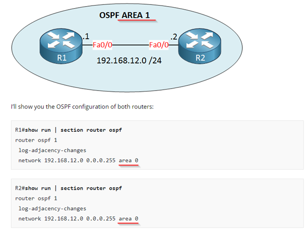
There is a tiny typo in a scenario “OSPF DR/BDR Election”. OSPF Area mismatch in the topology and configuration examples:
Thanks
1 Like
Hi Boris
Thanks for pointing that out, I’ll let Rene know…
Laz
Thank you Boris, just fixed this.
Rene
Hi Rene,
Thanks for the lesson..
R1#show ip ospf neighbor

Neighbor ID  Pri   State           Dead Time   Address         Interface
192.168.12.2  0   FULL/DROTHER    00:00:38    192.168.12.2    FastEthernet0/0
R2#show ip ospf neighbor

Neighbor ID  Pri   State           Dead Time   Address         Interface
192.168.12.1  1   FULL/DR         00:00:37    192.168.12.1    FastEthernet0/0
in the above logs why R1 is not a BDR? If we have a 2 routers in multi access network then DR and BDR should be selected but it is not the case here. Please explain..
thanks..
Hello Pushpender
Over a multi-access technology such as Ethernet, even if there are only two routers on the link, one should become the DR and the other the BDR. There are however some circumstances under which you would only see a DR, as in your output. It is not readily understandable why you have this output, but it may be due to one of the following reasons:
- The OSPF priority of R2 has been set to 0 so that it will never be elected as a DR or BDR.
- The network type on R2 has been set to a type that does not participate in DR/BDR elections.
Although it is unusual to have such configurations in a newly created setup, check these out and see if this is the case. I’ve labbed the first case up and was able to replicate your results. Let us know of your progress!
I hope this has been helpful!
Laz
Thanks Laz.. I missed to remove ospf priority which was configured on spoke route for non broadcast network type.. i have fixed it now
1 Like
Hi Rene/Laz
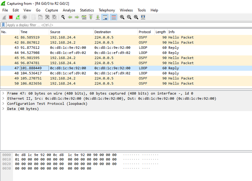
While capturing some of the packets I have been receiving below packets with “LOOP” protocol. Could you please explain to me what is this and what leads to origin of this packet.
Hello Tanya
The frames you see in the Wireshark capture with the Loop protocol are frames sent by the Configuration Testing Protocol (CTP). This is a part of the original Ethernet specification document from 1982 (Chapter 8) but it does not appear in any later IEEE documentation. The protocol is an obscure part of Ethernet whose function is kind of like a layer 2 ping that is implemented by the OS itself, and is not something that you can initiate yourself. Cisco equipment is known to use it, but very few other vendors do.
Some interesting links about this include:
http://www.mit.edu/~jhawk/ctp.html
I hope this has been helpful!
Laz
Hi Rene
I created 2 routers and establish neighbor relationship
I have a question. I understand that LSR/LSA process is reliable.
Router A will send a LSAck to Router B for a link state update from Router B.Will this be via multicast address or a unicast address ?
Hello Virgilio
Take a look at this post…
I hope this has been helpful!
Laz
Hi Laz,
Just want to know can we enable multicast filtering by enabling IP traffic instead of OSPF b/c we know ospf is IP traffic and uses protocol no 89 in ip protocol field?
Hello Pradyumna
Yes it is possible to resolve this problem by simply adding a permit statement like this:
5 permit ip any any
This will match OSPF packets as well. But this will result in allowing any IP traffic including multicast traffic, and EIGRP traffic and many others that you may not want to allow. By specifying OSPF in the access list you are only allowing OSPF packets to be exchanged. THis gives you greater control over what you are permitting and what you are not.
I hope this has been helpful!
Laz
Okay got it laz.
Thanks a lot
1 Like