Lagapides
to clarifyt
he IPv4 address-family is automatically enabled and will exchange routes if the neighbor command is found under the BGP configuration mode
this is how routes are exchanged?
Hello Michael
Yes, this is correct. If you configure BGP like this:
router bgp 12345
neighbour 1.1.1.1 remote-as 12345
OR
router bgp 12345
address-family ipv4
neighbour 1.1.1.1 remote-as 12345
the result is the same thing. By configuring without the address family configuration, you are using the default address family which is ipv4.
I hope this has been helpful!
Laz
Hi Rene,
In addition to your reply I did notice that multiple sub interfaces are configured on PE router being used for VRF’s. But where is the physical connection terminated or connected for the vendor on the router, as we have set multiple sub interfaces associated to one physical interfaces ?? Do we connect the wan connection on the L2 switch and set the L3 VRF configuration on the router over sub interfaces ??
Like example
 int gi0/0

no ip address
int gi0/0.10
ip vrf forwarding A

ip add 10.1.1.1 255.255.255.0

int gi0/0.20

ip vrf forwading B

ip add 20.1.1.1 255.255.255.0
Please confirm.
Hello Raja
In this lesson, there are no subinterfaces configured. Are you maybe speaking about a different lesson? Can you refer us to the specific lesson so that we can help you more effectively?
Thanks!
Laz
can i do vrf is-is and bgp mpls using 15.6 vrl router on my gns 3 and vmware ?
Hello Harshi
I haven’t actually tried the specific configuration that you are describing, but it may be worth experimenting with. I think that the best way to find out is to actually try it out. If you have this setup, and you attempt to do it, let us know how it goes!
Laz
hi Rene, if i have vrf blue and vrf red on a nexus 5k. and vlan 10 with ip 10.10.10.0/24 in vrf blue and
vlan 11 in vrf blue with same 10.10.10.0/24 is configured. How will a host on south side of nexus 5k, with its gateway in subnet 10.10.10.0/24 can be directed to use a sepcific vrf for its routing ?
in a scenario where vrf red is disaster backup to vrf blue, how can we make sure traffic is sent through vrf red not vrf blue
Hi Harshi,
How did you configure the “south side” of your Nexus? If the host is directly connected then you add the interface directly to the VRF.
Rene
Hi is there a way you can redistributes routes form one VRf to another without causing a loop?
I have an ISP that we connect to via out VRF this goes out to our WaN sites. full routing tables are populated in the WAN sites.
NOW the ISP has requested that we create a new BGP AS with them and migrate sites over, however I presumed that the ISP would filter the traffic in there cloud from the old AS to the new AS site by site.
The requested that I do it at my END , is it possible to have 2 VRF’s with the same prefix/route map or will this cause a loop?

I tried thugs
Hello Michael
Can you clarify whether both WAN connections will be functioning simultaneously? Is there going to be a cutover from the WAN site to the New WAN site or will both WANs be functioning at the same time for a certain period of time?
If you have 2 VRFs with the same prefix/route map, then yes, you can have them function at the same time. However, if you are wanting to redistribute routes between the VRFs, this may cause some problems if the IP address spaces within the VRFs are the same.
Take a look at this lesson for how to share some routes between multiple VRFs:
Please let us know a little more information with the questions I asked at the beginning so we can help you out as much as we can!
I hope this has been helpful!
Laz
Hi Rene/Laz,
Looking at some other learning material when configuring VRF-lite and having OSPF running between two or more routers apparently it’s recommended to add the command:
capability vrf-lite
Apparently this stops background process checking for BGP and you configure this within the OSPF process on the ISP Router.
Example below:
router ospf 1 vrf Customer-1
capability vrf-lite
network 10.1.1.0 0.0.0.255 area 0
Just to add for anyone adding this command in a live environment where an OSPF neighbour adjacency is already established on the process in question the neighbour adjacency will drop
*Nov 9 13:16:14.487: %OSPF-5-ADJCHG: Process 2, Nbr 10.1.2.1 on FastEthernet1/1 from FULL to DOWN, Neighbor Down: Interface down or detached
*Nov 9 13:16:14.583: %OSPF-5-ADJCHG: Process 2, Nbr 10.1.2.1 on FastEthernet1/1 from LOADING to FULL, Loading Done
What is your opinion on enabling this? is it something necessary or just recommended?
Hello Matthew
When an OSPF process is associated with a VRF instance, the PE performs the following checks:
- When a Type 3 LSA is received, the DN bit is checked. If this bit is set, the Type 3 LSA is not considered during the SPF calculation.
- When a Type 5 or Type 7 LSA is received, if the tag in the LSA is equal to the VPN tag, this LSA is not considered during the SPF calculation.
These checks are necessary for PE routers that are also running BGP. Now there are some situations in which these checks are not desirable, such as when VRFs are used on a router that is not a PE router (i.e. a router that does not run BGP as well). In such cases, the capability vrf-lite command should be used in order to trun off these checks and allow the correct population of the VRF routing table.
So this command is used in the specific situation where you are implementing VRFs in a router that is not a PE router, a router not running BGP.
I hope this has been helpful!
Laz
1 Like
Thanks Laz, very helpful.
1 Like
I have question can we use OSPF between ISP & CE1 even they have different AS numbers
Hello Dinesh
It seems that your question doesn’t correspond with the topology in this lesson, since we don’t have a CE1 router nor do we have different AS’es. However, your question is quite valid.
Technically speaking, when you have two routers in different BGP AS’es, it is possible to make them OSPF neighbors and have them exchange OSPF routes. However, this should not be done as it can introduce problems in routing, such as routing loops or sub-optical routing.
IGPs like OSPF and EIGRP have been designed to function only within an AS. BGP has been designed to function between AS’es. BGP should be the only routing protocol that exchanges routing information between AS’es, otherwise routing havoc can take place. ![]()
I hope this has been helpful!
Laz
Hi Rene,
i am new to VRF side configurations of cisco routers. I tried your topology in lesson in GNS3. I tried configuration for configuring OPSF in VRF enviornment in RED and blue. On the customer side when i configure command " router ospf 1" and on the ISP side configure command " router ospf 1 vrf RED", the ospf neighborship is not established, but if i use command " router ospf 1 vrf RED on the client side then ospf is established.
You told in the lesson that we dont need vrf with command “router ospf 1” on the client side but we need vrf command on ISP side. Can you help in this regard.
Hello Singhj
I tried to lab up your topology, and tried to replicate your results to see if I get the same thing as you. However, if I configure the ISP router with router ospf 1 vrf blue and I verify that the VRF commands in the interface are correct, and the network commands on both the ISP and the client routers are correct, I do see that there is an OSPF neighborship established. Note my configuration (my IP addresses are different, but the config is the same):
ISP#show run | sec ospf
router ospf 1 vrf blue
 network 10.10.10.0 0.0.0.255 area 0
ISP#show run inter gig 0/1
Building configuration...

Current configuration : 140 bytes
!
interface GigabitEthernet0/1
 ip vrf forwarding blue
 ip address 10.10.10.1 255.255.255.0
 duplex auto
 speed auto
 media-type rj45
end

ISP#show ip ospf neighbor

Neighbor ID     Pri   State           Dead Time   Address         Interface
10.10.10.2        1   FULL/DR         00:00:38    10.10.10.2      GigabitEthernet0/1
ISP#
You can see above the VRF config in the interface, the OSPF configuration, and the neighbor status. Below is the counterpart config of the blue VRF client, without any VRF components:
blue#show run | sec ospf
router ospf 1
 network 1.1.1.0 0.0.0.255 area 0
 network 10.10.10.0 0.0.0.255 area 0
blue#show run inter gig 0/1
Building configuration...

Current configuration : 115 bytes
!
interface GigabitEthernet0/1
 ip address 10.10.10.2 255.255.255.0
 duplex auto
 speed auto
 media-type rj45
end

blue#show ip ospf neigh

Neighbor ID     Pri   State           Dead Time   Address         Interface
10.10.10.1        1   FULL/BDR        00:00:39    10.10.10.1      GigabitEthernet0/1
You can see that there is no VRF configuration at all. Take a closer look at your config and see if there are any other issues that may prevent you from creating a neighborship between the routers.
I hope this has been helpful!
Laz
Hi Rene,
Could you please explain, how ping works when someone outside pings an interface in a VRF. How does the reply go back? Note that I am not ping from the VRF, instead the other way around.
Hello Vasant
The whole purpose of creating VRFs is to isolate one VRF from another so that communication between VRFs is restricted. So pinging from “outside” the VRF of the target interface is not possible. It’s kind of like VLANs for routing domains.
However, if you want one VRF to communicate with another, then you can use VRF Route Leaking, which can be configured either using static routes or using MP-BGP. Both of these options are described in the following lesson:
Now the only other way for communication to take place between VRFs is when using VRFs in combination with MPLS and MP-BGP to allow for overlapping address spaces, which is further explained in this lesson:
But this goes beyond simply communicating between VRFs…
I hope this has been helpful!
Laz
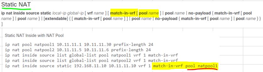
Quick question Laz ,
This new feature “match-in-vrf” do not have many people writing articles about it on google ;
I have been googling all day to find out what does Match-in-vrf pool natpool1 mean ?
As in the example given by Cisco in the following format :
ip nat inside source static 192.168.11.10 10.11.11.10 vrf 1 match-in-vrf pool natpool1
Especially, when you put two expressions together one after another , and especially in this order , ie “Match-in-Vrfl” first, then immediately followed by “pool natpool1” , what does it mean ?
As always, I greatly appreciate your time ![]()
(see Cisco example : https://www.cisco.com/c/en/us/td/docs/routers/sdwan/command/iosxe/qualified-cli-command-reference-guide/m-NAT-commands.html)Processing: AskTutor3.JPG…