VRF Lite Route Leaking

Hello Surendra

Well, it really depends on what you want to achieve. From my understanding, what this product provides is the centralized management and automation of security policies on Cisco devices. What the document is saying is simply that services and features such as ACLs, as well as VRFs can be automatically managed and provisioned. What you should focus on depends on what requirements you have for your business and your network.

It may be helpful if you share with us what you want to ultimately achieve. That way we may be able to suggest a course of action that will be more suitable for that need.

I hope this has been helpful!

Laz

Hi Lagapides,

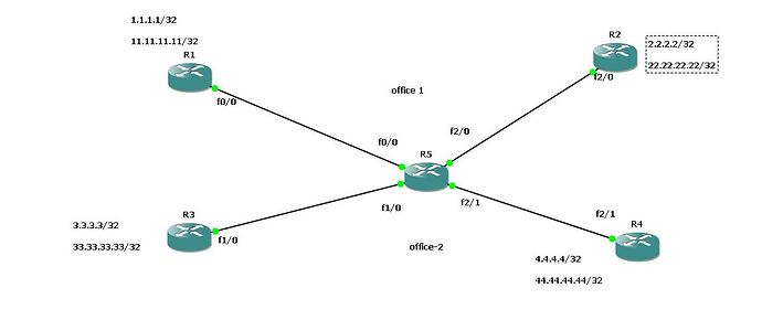
Above picture is my scenario. R5 router consider as ISP. i created two VRF on R5 router
vrf 1- office1 and vrf2- office2. Router R1 and R2 comes under VRF1- office1 & Router R3 and R4 comes under VRF2- office2.

Each Router i created two Loopback address for example R1 i created lop1-1.1.1.1/32 and lop2-11.11.11.11/32
For VRF1- office 1 i am using Ospf routing protocol
For VRF2-office 2 i am using Eigrp AS 100 routing protocol.

within the VRF i got full reachability’s. so far so good.

now i am going to leak routes from R1 router loop1 and loop2 to VRF office2.

so either i can go for static or M-BGP.

i will use static . first i have to create static route in R5 router

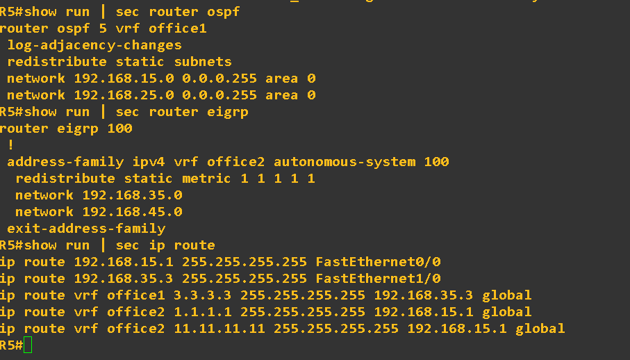
ip route vrf office2 1.1.1.1 255.255.255.255 192.168.15.1 global
ip route vrf office2 11.11.11.11 255.255.255.255 192.168.15.1 global

then i have to create global routing for NeXT hop address

ip route 192.168.15.1 255.255.255.255 fa0/0

after giving this command now R5 router under vrf office2 i have entry for 1.1.1.1/32 and 11.11.11.11/32 but R3 and R4 i don’t have any entry. so i can redistribute this static route into EIGRP. Now i am getting entry for 1.1.1.1/32 and 11.11.11.11/32 both R3 and R4 router but i am unable to ping 1.1.1.1 and 11.11.11.11 with source loop1(3.3.3.3) on R3
It will reach up to R1 router after that reverse traffic not happening. because R1 router does not have any entry for that sources ip .
i will create another static route in R5 router under VRF1-office1 points towards R3 loop1

ip route 192.168.35.3 255.255.255.255 FastEthernet1/0
ip route vrf office1 3.3.3.3 255.255.255.255 192.168.35.3 global

now i can able to ping from R3 router .

R3#ping 1.1.1.1 source lo1

Type escape sequence to abort.
Sending 5, 100-byte ICMP Echos to 1.1.1.1, timeout is 2 seconds:
Packet sent with a source address of 3.3.3.3
!!!!!
Success rate is 100 percent (5/5), round-trip min/avg/max = 4/38/72 ms

up to this what i did is everything correct i mean the design & what i did. because i am not sure i am going on right path or not (this only for static i am not using M-bgp).

i have 1 more question VRF route leaking means leak routes from 1 vrf to another VRF for an example another vrf have 5 sites so all the 5 sites can be able to reach that routes?

R5 routing configuration for (static)

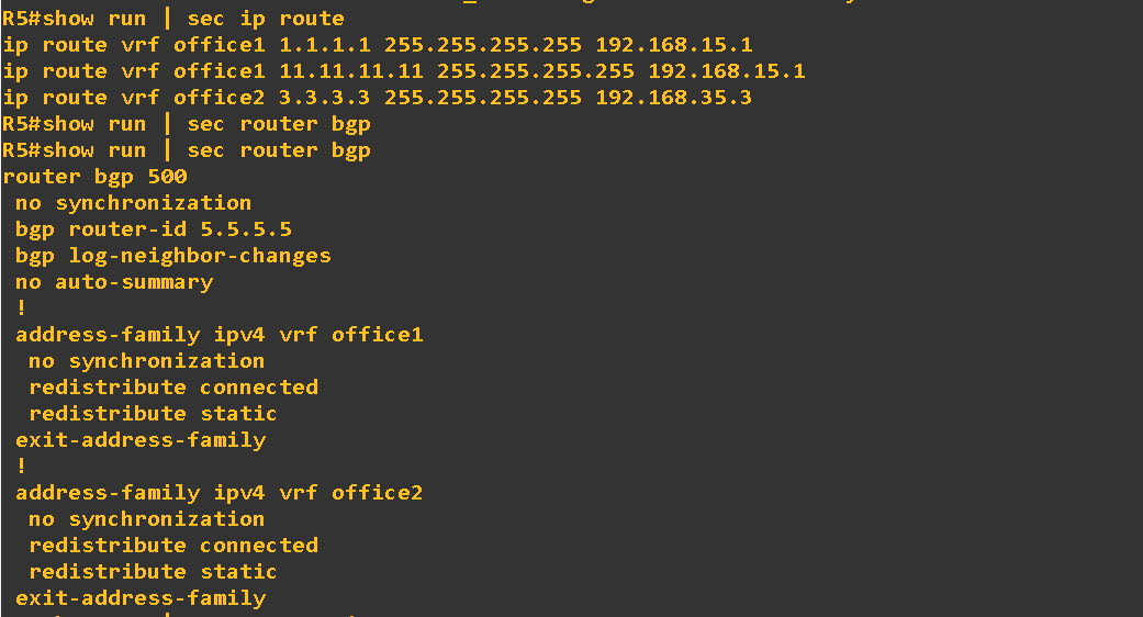
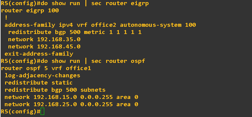
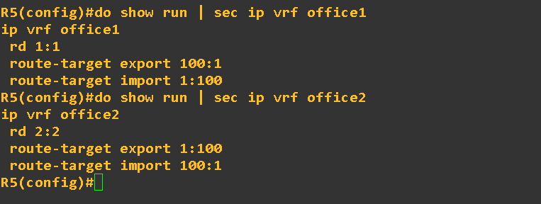
for M-BGP:

R5 router configuration for M-BGP

both Static and M-BGP is working fine. just want to know what i understand is correct or not and also design is good or not.

Hello Gowthamraj

In your description, it seems that everything that you did is correct in order to achieve connectivity between the specific routers.

Yes, route leaking will allow you to inform one VRF’s routing table of routes that exist in the routing table of another VRF. Now if you have 5 sites, this may mean that you are able to reach routes on all five sites, or you may be able to reach routes on fewer sites. It all depends upon which specific routes you choose leak.

From looking at the output, everything seems to be correct.

I hope this has been helpful!

Laz

Hi Laz,

Using MP-BGP method for route leaking we are redistributing vrf in to MPBGP but post redistribution vpnv4 route reach other end and there how it would be reaches CE b/c we are not redistributing it back in to VRF?

I am confused when redistribution comes in case of vrf b/c we normally we do redistribution in both direction link ospf in to BGP and BGP back in to ospf at other end?

Hello Pradyumna

Remember that any traffic going from one VRF to the other will only need to be redistributed once. For example, traffic from 1.1.1.1 to 3.3.3.3 will reach the ISP router, be redistributed from one VRF to another, and will reach 3.3.3.3. There is no need for a second redistribution.

Returning traffic will go through a similar redistribution process as well. Redistribution for both directions is taken care of by the redistribute commands found in each VRF.

I hope this has been helpful!

Laz

Mean at both PE router we need to redistribute in one direction only can say vrf to mpbgp. Back mpbgp to vrf will be taken care by redistribute command found in vrf !!

Am i right?

thank you lagapides.

1 Like

Hello Pradyumna

Yes, that is indeed correct! :+1:

I hope this has been helpful!

Laz

In the diagram below, a service provider has equipment located in a data center, and Customer A is also located in the same data center. A connection is made from CustA to SW1.

Both interfaces on SW1, as well as f0/0 on R1 are in VRF red.

In order for the customer to reach sites on the Internet, would routes need to be leaked from VRF red into the global routing table?

Hello Buck

First of all, I assume that all devices are routers, even though the middle one is named “SW1”. If F1/0 on R1 is in a VRF other than Red, then yes, in order for the customer to reach the Internet, you must apply route leaking. Route leaking will only take place in R1 where both the RED and the other VRF (whatever it may be) is assigned to F1/0.

I hope this has been helpful!

Laz

Hi Rene,
I did the lab on route leaking with the static method. I do not understand why pings from Red1 to Blue1 do not work unless I source it from the loopback interface.

Hello Ayong

If you ping from Red1 to 3.3.3.3, you are using a source address of 192.168.12.1. The router always chooses the IP of the exit interface for the ping as the source address when the source is not specified. This means that your ping will reach the destination because the 3.3.3.3 address is leaked from one VRF to another in the ISP router.

However, on its way back, it must go from Blue1 to Red1 using a destination address of 192.168.12.1. This packet arrives on Gi0/2 of the ISP router which is on VRF Blue. There is no leaking of the 192.168.12.0/24 network from Red to Blue, and since no inter-VRF routing can take place without leaking, the packet is dropped. If you take a look at the routing table of VRF blue in the ISP router, you will see that the 192.168.12.0/24 network is not there.

If you use a source of 1.1.1.1 (loopback interface) for the ping, then the return of the ping will reach the ISP Gi0/2 interface with a destination IP of 1.1.1.1. This has been leaked from one VRF to another, therefore it will be in the Blue routing table, and thus it knows how to route it and it reaches its destination successfully.

I hope this has been helpful!

Laz

1 Like

Thank you, Laz,
This was very helpful…

1 Like

Hi Rene/Team,
Thanks for the lesson. could you please tell me how to do route leaking from Global to Vrf using static routes? Is it possible to achieve it?

Regards,
Pushpender

Hello Pushpender

Take a look at this Cisco document that describes exactly what you are looking for…

I hope this has been helpful!

Laz

Hello Team
Im getting same output as esclated here, may i know why vrf RED learn and prefered 1.1.1.1 through MP-BGP from different vrf while 1.1.1.1 injected to red vrf on ISP side by same interface Gi 0/1,

Hello Nahro

I decided to lab this one up once again to clarify what is happening. In the first case, when we use static routes to do route leaking, we create a static route for the destination in the other VRF. It is these static routes that point to the global routing table that enable the route leaking.

In the case of using MP-BGP, the actual route leaking takes place using BGP. This means that the routes to the prefixes we want must first exist within the corresponding routing tables of the ISP router. In order to do this, we create static routes within each VRF that point to the desired destinations. For this reason, we have these static routes point to the prefixes in their own VRF.

Now the confusion comes with this statement in the MP-BGP section:

For each VRF, I will create a static route that points to the loopback 0 interface of the other VRF:

It should read:

For each VRF, I will create a static route that points to the loopback 0 interface within that VRF:

(I will let Rene know to make the correction to avoid confusion…)

Otherwise, the configuration in the lesson, as well as in the post linked above is correct. My initial post here was incorrect. So what are the results? Take a look at the routing table of VRF RED in the ISP router:

ISP#show ip route vrf RED

Routing Table: RED
Codes: L - local, C - connected, S - static, R - RIP, M - mobile, B - BGP
       D - EIGRP, EX - EIGRP external, O - OSPF, IA - OSPF inter area 
       N1 - OSPF NSSA external type 1, N2 - OSPF NSSA external type 2
       E1 - OSPF external type 1, E2 - OSPF external type 2
       i - IS-IS, su - IS-IS summary, L1 - IS-IS level-1, L2 - IS-IS level-2
       ia - IS-IS inter area, * - candidate default, U - per-user static route
       o - ODR, P - periodic downloaded static route, H - NHRP, l - LISP
       a - application route
       + - replicated route, % - next hop override, p - overrides from PfR

Gateway of last resort is not set

      1.0.0.0/32 is subnetted, 1 subnets
S        1.1.1.1 [1/0] via 192.168.12.1
      3.0.0.0/32 is subnetted, 1 subnets
B        3.3.3.3 [20/0] via 192.168.23.3 (BLUE), 00:36:04
      192.168.12.0/24 is variably subnetted, 2 subnets, 2 masks
C        192.168.12.0/24 is directly connected, GigabitEthernet0/1
L        192.168.12.2/32 is directly connected, GigabitEthernet0/1
      192.168.23.0/24 is variably subnetted, 2 subnets, 2 masks
B        192.168.23.0/24 is directly connected, 00:36:04, GigabitEthernet0/2
L        192.168.23.2/32 is directly connected, GigabitEthernet0/2

Notice that 1.1.1.1 is learned statically, and 3.3.3.3, which is the leaked route, is learned via BGP. If you look at the BLUE routing table, you will see similarly, that 3.3.3.3 is learned statically, and 1.1.1.1 is learned via BGP.

I hope this has been helpful!

Laz
1 Like

Dear Sir Laz
Thanks for your details explanation, now i have correct output result.

1 Like

Hallo Laz ,

if we have interface 0/3 on ISP Router and behind this interface there is PC 1 , if we ping lo1 1.1.1.1 on Red VRF from PC 1 how does the ISP Router Know how to reach the Address 1.1.1.1 ?I think since Interface 0/3 is on default VRf Table , so the ISP Router will not find any Route for 1.1.1.1 in global Routing Table ?do we need Static Route on global Routing Table which point to exit Interface that connected to Red VRF ?
Thanks .

Hello Mohammad

Yes, that is correct, you wouldn’t see any route to 1.1.1.1/32 in the global routing table, so PC1 in the configuration you described would be unable to ping 1.1.1.1. You indeed would need to create a static route on the global routing table, just like you did for Blue to reach Red and visa versa.

I hope this has been helpful!

Laz