Vrf Lite means Vrf without MPLS, why do you put a title like this VRF Lite Route Leaking?
What does LITE has to do with Leaking??
I learned fron you that you can do route leaking with vrf LITE and you completely messed me up because there is no such thing..imagine that i would be a joke at a random networking interview.
I’m sorry you feel that this has been misleading. VRF-lite is a feature that enables a service provider to support two or more VPNs, where IP addresses can be overlapped among the VPNs. VRF-lite uses input interfaces to distinguish routes for different VPNs and forms
virtual packet-forwarding tables by associating one or more Layer 3 interfaces with each VRF. VRF-lite is also termed multi-VRF CE, or multi-VRF Customer Edge Device, and is typically applied without MPLS.
Route leaking allows you to route some traffic between VRFs. Now when you perform route leaking in an environment where VRF lite is applied, as in this lesson, then it makes sense to call that “VRF lite route leaking.” However, if you are not happy with that title, then feel free to think about it as simply VRF leaking.
As stated in the lesson, route leaking directly between VRFs is not supported in any IOS version. However, you can leak routes from a VRF into the global routing table and then leak them again from there to another VRF. This can be done on IOS XR as well.
To find out more about VRF route leaking on IOS XR, take a look at this Cisco documentation that details how this can be done:
If you need any more specific information, feel free to let us know!
But could help me with below case, as you see in the static route of the IOSxr router I can add vrf table and add in the destination another vrf, isn’t this static route between two different vrfs?
According to this Cisco document, at least for Cisco IOS, it is not possible to perform route leaking directly from one VRF to another. However, this document is indeed old, and newer versions of IOS and IOS-XR and others may now support the feature. I have been doing some research to determine what the current capabilities of various platforms are to respond to your question.
In the meantime, can you please tell me what exact command you have issued in this output so I can research further? It’s not clear from your description or your screenshot. Please let me know so I can help you out further.
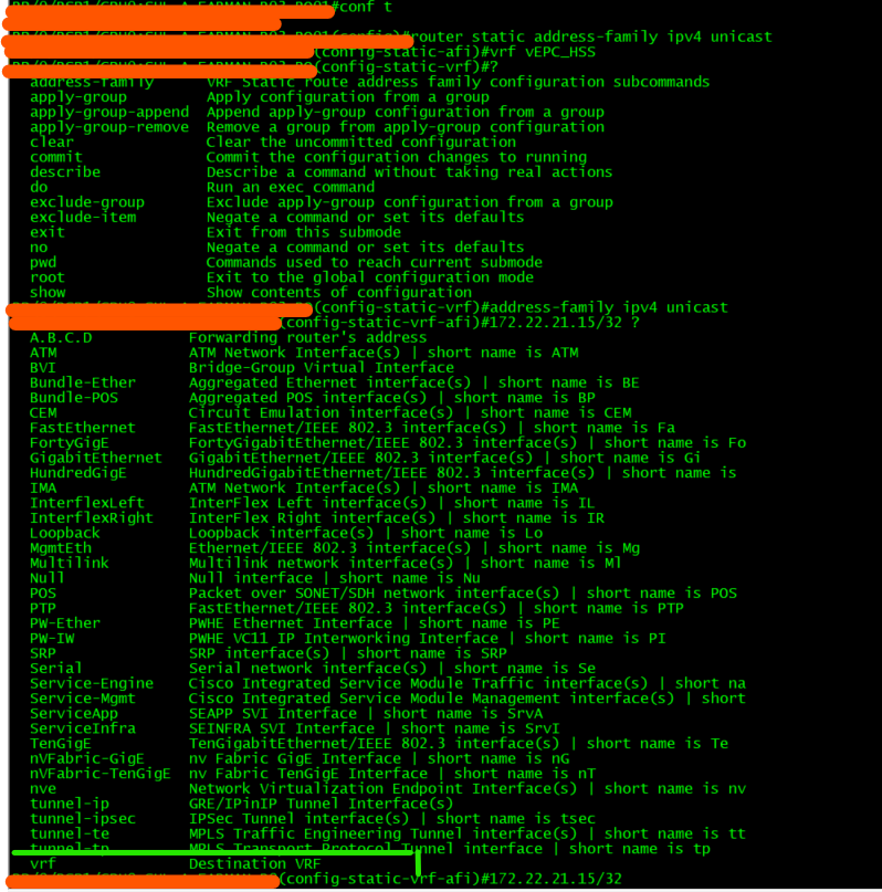
Thanks For your reply, yes it would be very helpful if you can find something approves that static route between two vrf is applicable or not, what I have shared is adding static route between two different vrfs opposite of what you mentioned in the lesson, the commands are in cisco 9k asr as follows,
Rx#conf t
Rx#router static
Rx#address-family ipv4 unicast
Rx#vrf WORD
Rx#address-family ipv4 unicast
Rx#X.X.X.X/X"destination ip"   vrf"any other VRF name in the router"    Y.Y.Y.Y"Forwarding router's address"
It turns out that it is now possible to do route leaking from one VRF directly to another. Here is some more documentation that shows this:
When the lesson was written, this was not possible, but it is a feature that has been added recently. I have spoken to Rene, and he will update the lesson accordingly.
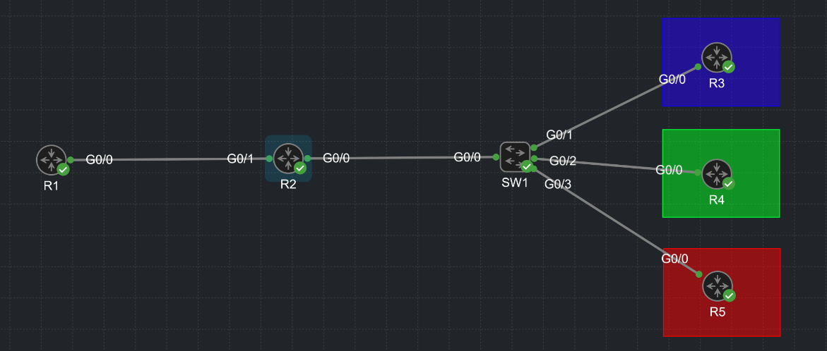
I’ve assigned the routers on the right to various VLANs and i wanted to keep them isolated, so I created a separate VRF for each of them which matches their color (BLUE, GREEN, RED).
However, if R1 wants to send anything to those VLANs, R2 drops the traffic because R2’s G0/1 interface is not in the same VRF as its VLANs.
How exactly can I allow communication here? I would have to assign all 3 VRFs to G0/1 somehow in order for it to work.
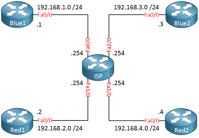
Hmm, it seems that the topology doesn’t fit the configuration. When applying VRFs, they are applied to a central router that connects directly to multiple other routers much like the below topology from the VRF Lite Configuration on Cisco IOS lesson:
In this lesson, you will notice that it is only the ISP router that has any VRF configuration. The other four routers are oblivious to any VRF configuration.
The only way to get your topology to work in a similar manner is to make R2 that central router that has the VRF configurations. The Gi0/0 interface will have subinterfaces, one on each VLAN, and each subinterface will correspond with a different VRF. That way each router R3, R4, and R5 will connect to R2 as if each one is connected to a different interface, and will be served by a different VRF.
However, you must understand the difference between the VLANs and the VRFs. VLANs segment a network at Layer 2, VRFs segment a network at Layer 3. Does that make sense?
Let us know a little bit more about the topology and the way you had planned to set up the VRFs so that we can help you further…
The confusion you’re experiencing is understandable and is due to the nature of VRFs and VPN routes. When you configure a VRF for a customer on your ISP router, you use the address-family ipv4 vrf BLUE command under the BGP configuration. This is because, from the customer’s perspective, they are just using regular IPv4 addresses.
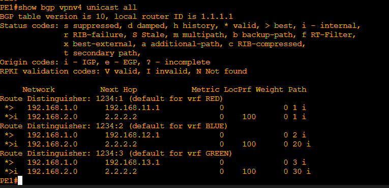
However, within the ISP network, these IPv4 addresses are transported using VPNv4 addresses, which are distributed using MP-BGP. This is why when you want to verify the BGP routes being advertised, you use the show bgp vpnv4 unicast vrf RED command. This command will show you the VPNv4 prefixes that are being advertised, which includes both the customer’s IPv4 address and the Route Distinguisher.
So address-family ipv4 vrf is used for configuration on the ISP router, while show bgp vpnv4 is used for verification because the ISP network sees these routes as VPNv4 addresses.
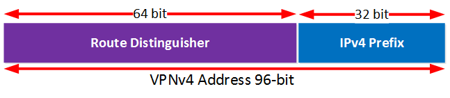
A VPNv4 route/address (96 bits) is simply a route that uses the route distinguisher (64 bits) combined with the advertised prefix (32bits). We know that the RD makes the prefix unique within the MPLS infrastructure as customers can use overlapping IP spaces.
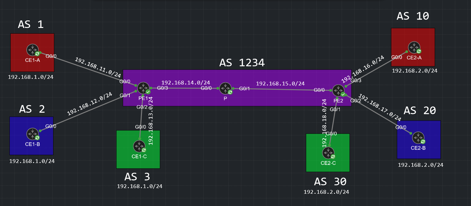
Here’s how it looks like in the BGP table and in the BGP advertisements. I’ve spinned up a simple MPLS lab in Cisco CML. I have 3 customers that we can refer to as RED, BLUE and GREEN. They’re connected to the same ISP that is identified under AS 1234.
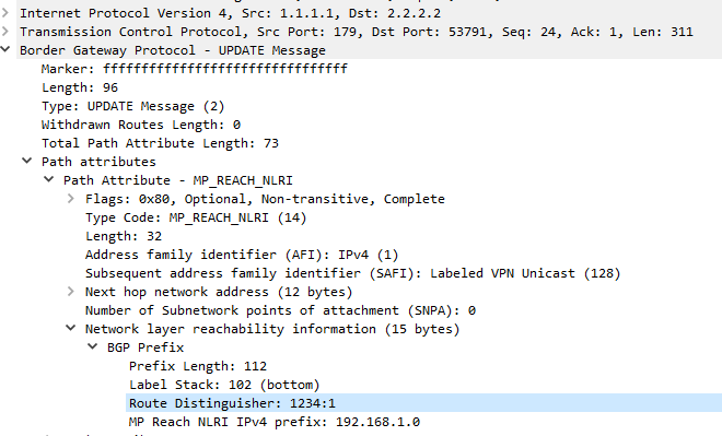
The RD is included within the NLRI information of the BGP UPDATE message together with the advertised prefix, as I’ve said above.
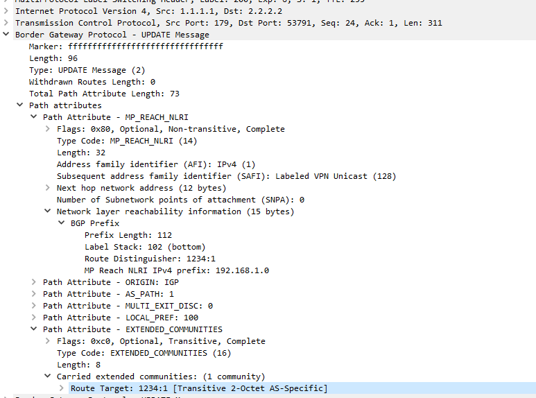
To answer your question about RTs, remember that RTs tell the router in which VRF should VPNv4 routes be imported and exported to.
So you have the unique VPNv4 route (96 bits) and now you need a way to tell the router which VRF to import/export the route to. You use an RT for this. The RT is nothing but an extended community value that is included within the Path Attributes of the route advertisement.
The Route Target (RT) is not included in the VPNv4 address. The VPNv4 address is a combination of a 64-bit Route Distinguisher (RD) and a 32-bit IPv4 address, making it a total of 96 bits. The Route Target is a separate attribute used in BGP (Border Gateway Protocol) for VPN membership information. It is not part of the VPNv4 address itself. You can see more about RDs and RTs and how they work with MP-BGP in this lesson.
When using VRFs with BGP address families would the activate command be required or is that already implied by default? when I configure a ipv4 bgp vrf address family?