This topic is to discuss the following lesson:
Hi,
Can you share this topology with a vPC configuration?
I read from DCCOR OCG, ‘two vPC VTEP switches appear to be one logical VTEP entity’ what this mean?.
This is the topology in figure 3-5:
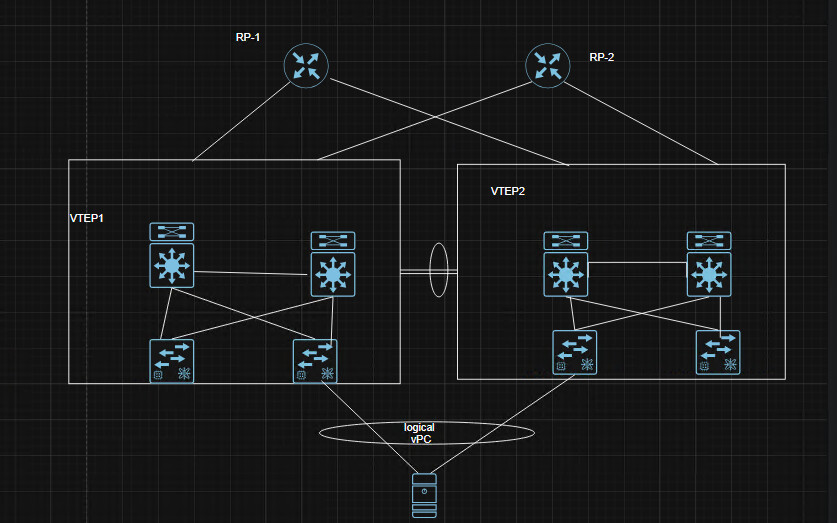
As I learned, leafs can’t be connected each other, so I suppose that vpc peer link travel through spines connections.
Can you help me understand how it works?
Hello Giovanni
It’s important to note that you are combining several different features into this topology. On the one hand, you have vPC, which creates a single logical VTEP, and on the other hand, you have VXLAN spine and leaf interactions.
When you create a vPC between two Nexus devices, you are creating a single logical device. This means that the two switches are viewed by other devices on the topology as a single switch with a single IP address.
Whatever features you enable on those two devices will function as if they are a single device, including the VTEP mechanisms.
Now let’s get to your topology. It looks like something is not quite right with the devices you have in each “VTEP” square. By definition, a vPC can be established between only two switches. Here, it seems like you have four devices in your VTEP box. I’m assuming the two devices on the bottom of each square should actually be outside of the VTEP box.
Secondly, it looks like you have some sort of LAG between the VTEP1 box and the VTEP2 box, something that doesn’t adhere to the rules of vPC, or the rules of VXLAN, since VTEPs should not be directly connected to each other, as you have also stated.
Finally, you also have a logical vPC between a server at the bottom and the two VTEP boxes. Such links should only exist between the pair of devices acting as vPC peers, and this is not the case here.
Can you share with us the source of this particular diagram?
Ultimately, it is possible to use vPC with VXLAN, and it is a good idea. But some caution should be employed. Take a look at this excellent Cisco Live presentation that shows many details about vPC and how to deploy it in a VXLAN environment.
I hope this has been helpful!
Laz
Thanks for your anwser.
This is a picture of this topology in my book, so I supose that it is not correct right?
Hi @Giovanni ,
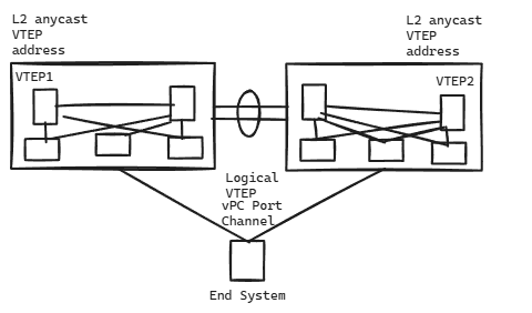
I replaced your image with a quick excalidraw image. If we upload book images, I could get into trouble (copyright issues).
Rene
1 Like
Hello Giovanni
Ah, I see… I believe that the confusion has to do more with the terminology used by the book rather than the actual topology.
On the one hand, we have the rule is that each VTEP is a leaf and cannot and should not connect to any other VTEP directly as far as VXLAN tunnels go. In the book they seem to have “violated” this rule by naming each of the logical entities “VTEP1” and “VTEP2” and connecting them together!
Now, when using vPC between two VTEPs, we can “bend the rules a bit” to allow two VTEPs to function as a single logical VTEP by creating a vPC between them. This is done by using an Anycast IP address for both VTEPs. In this sense, the VXLAN topology “sees” the two VTEPs as a single logical entity, even though they are two distinct entities connected via a vPC. So in essence, from the point of view of the VXLAN topology, the rule is not violated.
Now, the other thing that was not clear initially is the fact that each VTEP, as depicted within the diagram, is actually composed of multiple devices. This can be achieved assuming we’re using something like multilayer vPC. This is where you create a vPC between two pairs of vPC-connected devices. More about this can be found in this document:
http://www.cisco.com/c/dam/en/us/td/docs/switches/datacenter/sw/design/vpc_design/vpc_best_practices_design_guide.pdf
(page 11, chapter titled Multilayer vPC for Aggregation and DCI)
As can be seen, the end system sees the two VTEPs as a single logical VTEP, and so does the VXLAN topology.
I hope this has been helpful!
Laz
1 Like