Thanks a lot Rene…
Azm
Thanks a lot Rene…
Azm
I just went through the lesson. I don’t understand the part which says that - “layer 2 links should be configured between the distribution layer”. The reasons are given. But i don’t understand that part. Could you please help me with it ?
Hi Sriguruprassad,
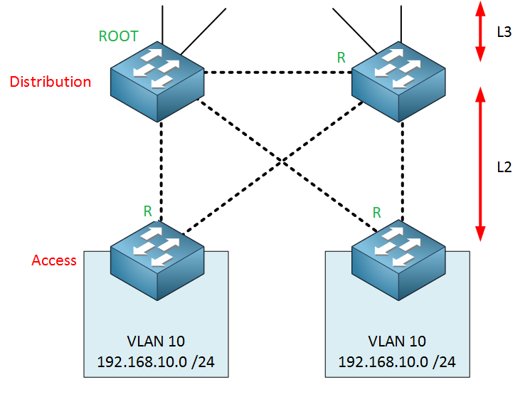
Let’s look at just one example why you might want to use L2 between the distribution layer switches. Consider this design:
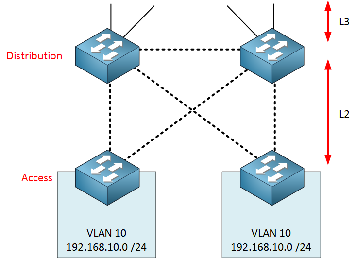
In this design, we have VLAN 10 on both access layer switches. All links on the distribution and access layer are layer two links.
Think for a minute about spanning-tree…let’s say that the left distribution switch is the root bridge. What will be the root port on all of our switches? Something like this:
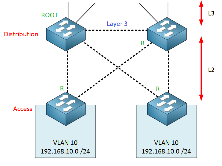
Now imagine we have an L3 link in between the distribution layer switches:
Since the link in between the distribution layer switches is now L3, the distribution layer switch on the right side will select another interface as the root port for VLAN 10.
Now imagine you configure something like VRRP…this means that all VRRP traffic from the right distribution layer switch goes through the access layer to get to the left distribution layer switch. Not a good idea ![]()
Hope this helps!
Rene
Hi Rene,
i was struggling with the parts:
If one of the uplinks from the access to the distribution layer fails, VLAN 10 could become isolated.
The switches on the distribution layer will use a protocol to create a virtual gateway IP address. We need layer two connectivity for this.
If the link from Access switch 1 (left) towards Distribution Switch 1 (left) fails, then the link Access Switch 1 → Distribution switch 2 is used. If there is no L2 link, the link Distribution Switch 2 → Access Switch 2 will become the root port and traffic is forwarded to the Distribution Switch 1 (HSRP active node). This is not a good design, but the Vlan 10 would not be isolated.
Please correct me if i’m wrong.
Many thanks,
Oliver
Hello Oliver,
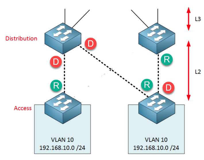
You are correct, VLAN 10 won’t be isolated since it can still go through the distribution layer switches. Here’s a picture to visualize this in case anyone wonders what this is about:
In the picture above, there is no L2 link between the distribution layer switches and one uplink from the access layer to distribution layer switches failed. If the left distribution layer switch is the root then traffic will go through the access layer like this.
I just removed the sentence about isolation, thanks for sharing!
Rene
Hello Rene,
thanks a lot for clarifying. ![]()
Cheers,
Oliver
what is the backplane in the specification and the word require high bandwidth and throughput, what does exactly mean
Hello Pipat
The backplane is the name given to the internal circuitry of a switch which acts as the pathway between individual ports. If you have a switch with 48 1Gbps ports, and you have computers connected to all of those ports, theoretically, you should be able to have 24 computers each sending 1 Gbps of information to the other 24 computers simultaneously. This requires an internal bandwidth on the backplane of the switch of 24 Gbps in each direction, for a total of 48 Gbps. If the switch has additional uplink ports, those must also be taken into account as they can add traffic to the backplane.
The total backplane bandwidth should be high enough in order to accommodate the expected traffic on a switch. Now the total bandwidth of all interfaces is usually higher than the available backplane bandwidth, because a simultaneous usage of full bandwidth on all ports is highly unlikely. A balance is struck providing enough backplane bandwidth to accommodate most situations.
I hope this has been helpful!
Laz
Hello. Why are layer 3 switches used in access layer? (according to the first chart of recomended models).
Thank you!
Hi Eilu,
Hope you are doing good:smiley:
(according to the first chart of recomended models).
which chart you are talking? can you paste the screen shot here ? actually i am trying to find out your answer but not able to understand which chart you talking.
Thanks & Regards,
Arindom
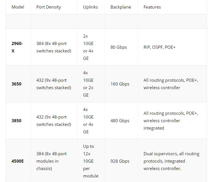
I believe he is talking about this chart.
There are layer 3 switches in the chart but this is because those are the “lower end models” that Cisco has to offer. They can run as layer 2 switches and not utilize the layer 3 functionality. As switches have gotten more powerful layer 3 functionality has been easier to put into a switch. A big consideration of what switches you might use in a network is the size of said network. A tiny network might only need 2960-X’s for the core, distribution, and access layer. I hope this helps!
Thanks,
Scott
Hello Eliu
You can use Layer 2 switches at the access layer, and that would be fine. However, keep in mind that if you have multiple VLANs running on a single switch, any communication between those two VLANs will have to be sent up to the distribution layer to be routed and then back to the access layer switch once again, to reach the destination.
Now for some networks, that’s fine, however, if there is much inter-subnet communication in a network between devices that are connected to the same switch, it may be worthwhile (although more expensive) to provide that routing within the access switch itself. It all depends on the applications being used and the expected traffic between such devices.
Remember, if your uplinks are being used to transfer data between two devices on separate VLANs on the SAME switch, you may be using up valuable bandwidth of the routing will have to take place at the distribution layer. It all depends on your network design, uplink bandwidths as well as the expected traffic.
I hope this has been helpful!
Laz
Hi Rene
If we have multiple vlans environment , then what about SVI creation. SVI will be created on each Distribution layer switch or only single distribution layer switch.
Hello Muhammad
The VLANs that are used by each of the distribution and access switches will be created within them. However, the SVI for each VLAN should exist on only one device, typically the distribution layer switch that serves the VLAN. That way there is only a single location where inter VLAN routing takes place. Now if you use a redundant gateway protocol such as HSRP, then you will have two devices (or more) with an SVI interface for routing purposes, but they will share the responsibility using a virtual IP. You can find out more about HSRP at this lesson:
I hope this has been helpful!
Laz
Hi Rene,
Could you give an example of commands sequence for calculation of a switch fabric capacity? e.g. Cisco 2960 series. Thanks in advance.
Hello Vadim
There are no commands that you can use to determine the internal capacity of a network device. The best way to find out what you need is to look at the datasheets of the devices in question. Specifically, the 2960 series can be found here:
Based on this document, you can look at two values that will give you information about the fabric speeds:
I hope this has been helpful
Laz
Hello Rene/Laz
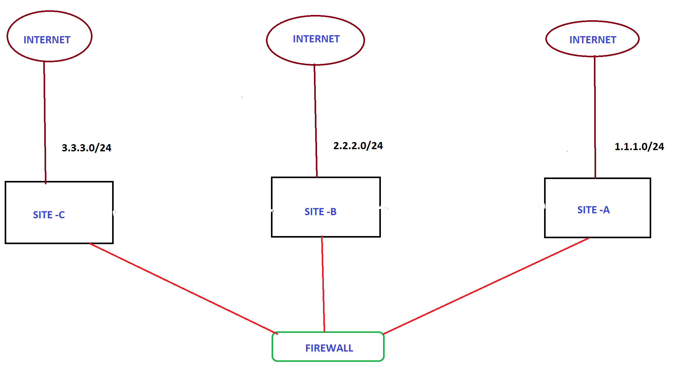
I have some questions and I am going to use the below diagram as the reference.
In this topology, I have three different sites that are geographically located at three different places. As you see in the diagram, every single site has their own internet connection and they are hosting their public facing servers by using their own Public IP addresses. Now the requirement is to have internet redundancy for every single site. For instance, if the internet connection at
SITE -C goes down, it should be able to use SITE -B or SITE -C as the backup path. In this situation, how can I have redundancy for public facing servers among these three sites. Meaning If the internet connection goes down at
SITE -C, still internet traffic should be able to access the public facing websites that are being hosted by SITE -C by using SITE -B or SITE -C internet connection. Please shed some light on it.
Thank you so much in advance.
Best Regards,
Azm
Hello AZM
I order to achieve such redundancy, you will need to use BGP in a dual or multi-homed configuration. Specifically, this means that the IP addresses of your web servers must be advertised via all three ISP connections, with varying attributes to indicate which is the primary, secondary, and so on, route to get to your servers.
Now there are several “administrative” issues involved here. If your public IP addresses are provided by your ISP, and you have different ISPs at each site, you may not be able to route IP addresses of one ISP via another ISP. If the public IP address range is your own, then you can advertise this freely however you like, assuming you are running eBGP between your equipment and each ISP’s equipment. Much of what you can and can’t do in this area has to do with the policies of each ISP, and for this reason, an extensive chat with them describing what you want to do will go a long way in finding the best solution.
In such a situation, controlling outbound traffic is easy. If an ISP fails, you route traffic via the secondary route. You have control over your own equipment to be able to reroute such traffic. The challenging part of incorporating such redundancy that you describe has to do with incoming traffic. Such a situation requires you to attempt to control incoming traffic, that is, the way that each ISP will route traffic that is destined for your servers.
The first rule about controlling inbound traffic is Attributes that you would use to that you do not have ultimate control over how traffic enters your BGP Autonomous System. All of your eBGP peers can override all of your attempts to influence incoming traffic. Having said that, however, there are four ways in which you can attempt to influence incoming traffic to achieve the redundancy you need: Leaking more specific routes, MED, AS-PATH prepending and Community/Local pref agreement.
You can find out more about each of these in Unit 3 of the BGP lessons. Here’s a link to the attributes lesson:
Also, you can find out about the dual and multihoming scenarios at this lesson.
I hope this has been helpful!
Laz
You the man Laz!!!
Azm
I was wondering if someone could shoot me some advice on Network design. More Specifically collapsed core/distribution model with Multiple Vlans ( including Voice ). For example for the attached Network diagram, I’m trying to decide best route:
New_Design.pdf (80.0 KB)