The following lesson includes network design principles that you can use for such projects:
Having to do with your specific question, it depends on your implementation. For most campus networks, and based on your diagram, I would prefer to have routing occur at the core/distribution layer and have the DHCP servers there as well. DHCP and routing should take place in the access layer ONLY if the network is exceptionally large, offloading some of the L3 implementation from the distribution layer to the access layer. However, since you’re implementing a collapsed core model, this doesn’t seem to be the case here.
What IP addresses you use to address the access layer switches in this case is irrelevant to the design, since access layer switches in this scenario would only provide layer 2 functionality.
Hi All
For my College project I have to design a network for a factory. I have reviewed the lesson on campus design (but my network is similar to jsut having 1 building on the campus). I have to configure the network using packet tracer 6.2.
I have decided that I am going to have at least 5 switches, and use trunking to allow the switches to talk to each other. I would also like to build in redundancy.
I will have 3 standard vlans, vlan 10 for network Management, vlan 1000 for discards, and vlan 999 for trunking.
So ideally, I want all the switches to use the same ports for network management, so was thinking for instances that I would always assign ports fa1 for trunking, and ports fa2 and fa3 for Network management, and I would do this on all swicthes to be consistent.
I do have a vlan plan, but I am struggling with getting some sort of consistency, and am not sure the plan is the best. Apart from the 3 basic vlans, (trunking, discarding, and network management), would you then limit the vlans on the switches? Currently I seem to have a lot of vlans on different switches which seems to be a mess.
I am using the C3560 switch as it has 24 ports.
When you build the network do you start by making sure the switches can talk to each other , or do you configure each switch with its vlan first?
Let me start from the end of your post. Where do you start? Start by drawing out your design on a piece of paper. It often helps me to see the boxes and connect them physically with lines so I can see the network taking shape. Now I don’t know how much detail you are given about the factory in order to decided how many switches you’ll need, but I’ll include more detail than you’ve given, just for completeness. Ask yourself the following questions:
How many users are in the factory? How are they distributed? Will five switches of 24 ports each suffice for all the users and their distribution throughout the building? Remember that users cannot be more than 100 meters (cable distance) from each switch.
Switches should be connected to each other via trunks that carry (initially) all VLANs in your topology. I say initially because in the future you might find that some VLANs are limited to a certain area of the network, and you can remove them from some trunk links to avoid unnecessary broadcasts reaching parts of the network that will never use them.
The physical connections can be made in one of two ways. Either you connect all five switches in a ring topology, and have one of the switches connect to the Internet, thus providing redundancy if one link breaks, or you can have a single switch as the central one, and make two physical connections between that central switch and each of the other four switches, providing redundancy this way. This is somewhat more resilient, but costs more in links and port usage than the first option.
Next, you can choose how many VLANs you will use. Will you separate the network into VLANs based on location or on department? You can make an administration VLAN, a marketing VLAN, a manufacturing department VLAN, a Voice VLAN etc. But you should have a management VLAN and a native VLAN. You can configure these VLANs in all switches, and allow all VLANs across the trunks so you can add them to any port you like.
A note about the management VLAN. Why do you need physical ports for the management VLAN? You can just create an SVI port on each switch within the management VLAN and allow access to each switch via IP addresses assigned to those ports.
Also, what do you mean by VLANs for “discards” and “trunking”? I assume you mean the native VLAN for discards, meaning frames without tags. A trunk on the other hand is configured to carry multiple VLAN, so a specific VLAN is not necessary to specify for use with a trunk.
I hope this gives you a good starting point. As you begin your design, if you have any more questions, please feel free to ask!
Hi Laz
thanks. Thats very useful. The factory is 100m by 60 m over two floors. (But the upper floor has only 100m x 10 m of floor area.
For the switch topology I have followed the example in the Campus Network Design basics. I have 1 switch block with one core switch, two distribution switches and 4 switches for access.
These are all connected via trunking. So I am happy with this aspect, as I have built in redundancy. I have configured all these switches (But I only need to configure 5 ).
I would consider adding a second core switch (But this may be overkill). I might add this in at the end (time permitting). Of course , this being a virtual exercise, cost is not an issue.
I have configured the network manager vlan 10 wjich is assigend 2 ports fa1 and fa2 on each switch.
We do not actually know the number of users in the factory, but we do know that there is about
10 offices , a showroom, and a testlab, plus the factory floor. We do not have to configure ip phones fortunately.
Our lecturer always used physical ports for the management lan, so this is why I am using a port for this.
Again my notes always use vlan 999 for trunking and vlan 1000 from discard. As I understand it, these do not need to be related to physical ports.
I will definitely have a manufacturing vlan, and an office vlan. My instinct tells me its best to separate out the office vlan by floor, and configure the ground floor and first floor vlans to talk to each other, I think I need a vlan for the warehouse, one for the showroom, and one for the testlab. I will also need to set up a wireless printer on each floor, and a wireless router for office staff, which should connect to the network. I also need to set up a guest wireless router which should have no access to any office equipment. Of course I also have to set up passwords on switches, ntp, syslog, dns, etc.
(As you can see , this is quite a comprehensive exercise for 1 module in a part-time course).
Thanks for the help and advise. I think I am on track at the moment.
The whole project does indeed appear to be very comprehensive. It’s great that you’re tackling it so well and integrating everything that you’ve learned. I wish you success, and let us know how it turns out!
I’d like to run L3 switching between my core and access layer switches, but am missing something.. Attached is a first draft of a diagram. I understand having one Vlan per switch and it stays there, and that’s what I plan to do, but what if I have a Vlan 40 that is my servers and printers vlan and I need vlan 40 ports on each of the switches shown?
Or would it be best to config the Port channels at a L2 and trunk them, and forget this idea? I will not be doing a lot of interoffice communication. Most of my traffic is internal endpoint to cloud..
The answer is: “it depends”. The idea of keeping a VLAN confined to one switch is not an unbreakable rule. It is a general guideline that is good to follow to avoid needless transmission of broadcast traffic to areas of the network that wouldn’t use it. If you can achieve it, it’s great. If the needs of your network require it, then use it, but to a minimum as much as possible.
Having said that, if you have VLAN 40 as you say, and you have several servers on that VLAN, it would’t be a good idea to connect those servers to various ports on the access switches. If this was done, then your links between the core and access switches would be weighed down with additional traffic. Even a device on the same access switch as the server would have to connect via the core, which means communication needlessly going up the link and coming back down the same link, wasting bandwidth. Servers should be consolidated onto a single (or more for redundancy) switch within the datacenter, which alleviates any problems of VLANs spanning multiple access switches.
As for printers, some administrators keep them in the same subnet as the users while others separate them into different VLANs. If you keep them on the same VLAN as the users, it’s easy to confine the VLAN to a particular access switch. If you want to put them in their own VLAN, it helps in the organization and administration of the network but it doesn’t provide any more benefits than that. Even so, if you choose to do so, in most cases, printing over the network doesn’t impact the network very much (except if you have high volume printing due to the nature of your business) so spanning VLANs for printers is not a big issue.
I am all for routing between the core and access layer. It gives you more flexibility and options for security (access lists can be applied at the location where the routing takes place for example). However, I would still make the aggregated links into trunks to allow for the management VLAN to pass. This allows all network devices to have an IP address in a single subnet just for the purposes of management (CLI access via Telnet or SSH).
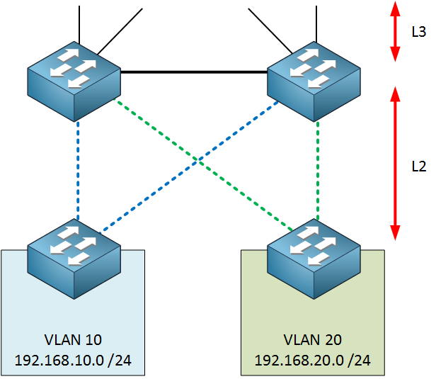
In the previous topology to this one shown in the lesson, VLAN 10 existed on both access switches, and the distribution switches between them had an L2 link. This means that there was a loop on VLAN 10 between Access switch 1, Distribution Switch 1, Distribution Switch 2 and back to Access switch 1. The same was true of VLAN 10 on Access switch 2.
In comparison to the previous topology, this topology has an L3 link between the two distribution switches. This means that there is no longer an L2 loop between the switches mentioned. This means that both uplinks from the VLAN 10 access switch can be used simultaneously without causing a loop.
Now in order to load balance between these, we require that some devices use an SVI on Distribution switch 1 as their gateway and some use an SVI on Distribution switch 2 as the gateway. This way, traffic can be separated between the two links.
From the moment that an L3 link between the distribution switches exists, we can’t use technologies such as link aggregation or HSRP, and since the access switches are L2, routing cannot be used to load balance. The fact remains though that both links can be used simultaneously.
How would the 2 tables look for Access switches and those of Distribution/Core switches look if you were to take into consideration the Nexus series of Cisco switches?
Nexus switches are specifically designed for use in the core of the network as well as for datacenter implementations. All Nexus switches would definitely go in the distribution and/or core layer table. They have features that are specifically geared towards streamlining of network core maintenance, harmonizing configurations across multiple platforms, providing redundancy and resilience to the network, as well as delivering high performance hardware such as CPUs and memory, for demanding operations including QoS, a multitude of access lists, and load balancing to name just a very few.
First of all, I would like to say thank you for all your work, you really have mastered networking and simplify it very well.
I’ve got a question about the Backplane of a switch. I’ve read a few articles about it but they are not very clear. I’ve got 3 questions regarding the backplane:
What exactly is the Backplane?
How do you calculate the Backplane bandwidth/speed/throughout?
How do you select the switch with the correct Backplane for each of the layers in the Campus Design? (Core, Distribution and Access Layer)
I guess its the same thing with routers. I’ve seen some specification data sheets for routers and they also mention the throughput of the router. How would you select the correct router with the correct throughput speed based on the bandwidth requirements of your network? How does the calculation work? The company that I work for at the moment are in the process of adding an MPLS network and the project has been assigned to me. I’m trying to select the correct router for the MPLS Edge but don’t really understand the “throughout speed” of the router to make the correct selection.
I would really appreciate if you can explain in simple terms.
Just to clarify on the MPLS network, we are going to use an MPLS network for our WAN connection to branch sites, so not building an actual MPLS network. I’m trying to select the right router for connecting into the MPLS network at the HQ site.
The backplane of any device is comprised of the internal pathways between the physical ports. This is especially important on devices that have a lot of ports on them. For this reason you can understand that the backplane speed is more important on a switch than on a router. Why?
Well let’s consider a 48 port GigabitEthernet switch. Each port is capable of 1000Mbps. Now imagine that you have 48 hosts on the switch, and the first 24 hosts are sending data at 1000Mbps to the second 24 hosts. This means that internally, the switch is allowing a data flow of 24 Gbps through its circuitry. If you take into account that this traffic should be bidirectional, you should be able to allow up to 48Gbps in order to fully take advantage of the available speed on all available ports. And what if you have four 10 Gbps uplinks? What if data is also being sent through those at full speed at the same time? All of this simultaneous usage of internal bandwidth is handled by the backplane.
There are no physical pathways between the switch ports, as frames are switched logically based on MAC address (and if it is an L3 switch, by IP address as well). The capability of the internal circuitry to accommodate all of the data being sent and received from all of the interfaces is measured as total throughput. Now the backplane speed becomes even more important if you have chassis switches that can take multiple modules increasing the number of ports to 144 and beyond.
This is not something that you calculate, but it is a specification given by the manufacturer of a device’s capability. You can however calculate what backplane speed you believe you will require for your network. Questions you should ask include:
How many hosts are expected to be connected to this device?
What kinds of services/applications will these users be using? What kind of traffic patterns can I expect from each user?
Are there times where I will require simultaneous high speed traffic capabilities from all users?
If you will be running traffic-demanding services, such as multicast HD or 4K video, large file transfers etc, simultaneously on many hosts, then a higher backplane speed is required. Otherwise, for normal operation, because traffic usage tends to be random, and it is very rare that all hosts will be demanding large amounts of data simultaneously, backplane speed should not be an issue.
Keep in mind that if you have only a few ports being used on a device (such as on a router), the backplane speed is not of particular concern. For your WAN router, you may be using two to four of the ports. If they’re 10GE ports, then the maximum backplane throughput you would need is 40GE, a value that is not excessively large. If you’re only using two ports, then the backplane will never be taxed more than the speeds of those particular ports, so it becomes a non-issue.
Due to the large number of users they support, the backplane throughput is much more important on switches than routers.
A question about this topic.
As Renè said :
“Don’t connect the access layer switches to each other.”
“If possible, don’t span VLANs over multiple access layer switches.”,
But what is the best practise if a lot of computers/devices are needed for one specific vlan?
The purpose behind this principle is to have all communication from an access switch go directly to the distribution layer. Access switches are the part of the network that have the most devices connected to them, so they are busy switching traffic between a large number of hosts. If you connect one access switch to another, then you are enabling an access switch to function as a transit device for traffic from hosts on another access switch. This is an unnecessary burden on an already burdened device. Uplinks to the distribution layer will usually be of higher speeds, and will usually be redundantly connected to two or more distribution devices. In addition, by having each access switch uplink to the distribution layer, you have more control over the kinds of features you can apply to that traffic at the distribution layer (access lists, QoS, etc).
The principle that Rene is expressing here is “try to keep VLANs as localized as possible”. Ideally, although this is rarely possible, try to keep a VLAN within its physical switch as much as possible. The reason for this is to minimize the scope of a VLAN so that broadcast traffic does not needlessly cross trunks to reach switches where such communication will be discarded. There are however always exceptions to these rules, and you may have a single PC in another building of your campus that needs to be on the same VLAN as a group of PCs in another building. What do you do? Well, you create the VLAN. But this should be an exception, and should not be the norm.
If you need connectivity between devices in various areas of the network, it’s a good idea to route between them rather than put them all on the same VLAN. From the ground up, you should design your network so that you don’t need to span a single VLAN across multiple access switches and across the distribution layer. This is a fundamental design principle that should be employed from the design stage.
I’m not sure what you mean by “visualize” the distribution layer. The distribution layer is used to connect the access layer to the core layer, and to provide routing between access layer VLANs. Can you be more specific in your question so that we can help you further?
Your design and your explanation are both very comprehensive, and I commend you on creating the topology in GNS3 before implementing it on a production network.
My number one concern about this topology is redundancy. All points are single points of failure, if any single device goes down, the network will seriously be impaired. This of course is a policy decision based on the cost of such redundancy and if it is worth it for this particular application.
Secondly, you have a VPLS tunnel between VPN ant TELCOS, and based on the physical connections described in this diagram, this tunnel goes through the FIREWALL device. This means that traffic going over that VPLS tunnel with a destination of the VMs will reach TELCOS and be sent back to FIREWALL to reach the VMs, which uses additional bandwidth on the link, bandwidth that can be avoided. I would suggest, for redundancy, and to use bandwidth more efficiently, to provide a physical link between the VPN and the TELCOS devices if their physical locations allow this.
Those are my comments from a high level perspective, @ReneMolenaar may also want to further comment on the design you have put together.