hello Mr. Laz,
thank you so much for your help. It is really important what you said. I will write everything ![]()
Stay safe
Mina
1 Like
Hi,
what is the connectivity
between core and distribution layer .
is it Layer 3 or LAyer 2 ?
Thanks
Hello Sims
This depends upon several factors, one of which has to do with the size of your network. Typically for smaller networks, you will find that routing takes place at the distribution layer. This means that all communication between the distribution layer and the access layer, as well as that from the access layer to the end devices all takes place at layer 2. Any device that needs to communicate with another device in another subnet will be directed to the distribution layer for routing.
As your network gets bigger, it may be beneficial to move routing lower in the hierarchy, even down to the access layer.
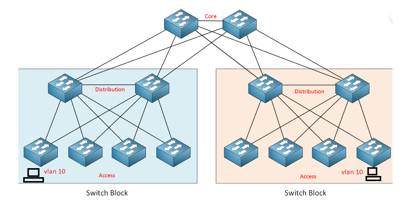
This is explained in the lesson in more detail about halfway down, where Rene begins to speak about switch blocks. Because this lesson has no sections, I can’t link you directly there, but you can find it by searching for the sentence: “When the network grows, we create so-called switch blocks.” From there on, Rene explains the logical topology between the distribution and access layers in detail.
I hope this has been helpful!
Laz
Hello Guys,
I really enjoyed reading this topic and it was so beneficial. It seems more time is needed to be professional in network design.
My company is planning to expand its business to a new site with 6 floors and a capacity of 140 people work in that building; and they give the network design job to a contractor however in my humble knowledge the design seems to be very poor.
Local Area Networks
The company needs to have three separate LANs and they want them to be segregated as each LAN has got its function.
They need a LAN for data and voice.
The other LAN is for access control system and cctv.
The last one for emergency system.
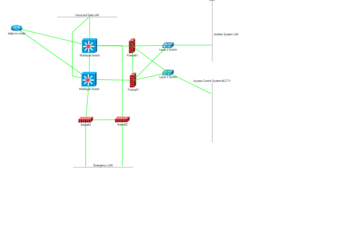
The reply came from the contractor with two MLSs, One wan router, and at the end of Emergency and Security LANs before connected to the MLS are connected to firewalls.
In my opinion there is an overkill of firewalls. Can I reduce the number of the firewalls hence reduce the cost and the segregation is doing the same purpose.
Another question In case I need to have a data center is it better to have it in the voice and data LAN or to have its own LAN I mean physically not VLAN (its own cables and switches)?
It looks more or less like the below figure
Hello Abdalla
Looking at the diagram you shared and the explanation of the topology, it is interesting that these firewalls are placed in such a location, however, such a design is not unheard of. The location of the firewalls is based upon the security requirements of the LANs that are placed behind them.
So in your topology, you have the Emergency LAN, the Access Control System and CCTV LAN, and the the “Another System LAN” all behind firewalls, which are delivering security policies to these LANs, and protecting them from potential attacks that make take place from the network internally. Because these are indeed mission-critical systems, the location of the application of those policies is good.
Another question that comes to mind, is how will this be implemented physically? Does each one of those firewalls correspond to a single physical device? If so such an arrangement delivers firewall redundancy but may be expensive. You can replace each pair of firewalls with a single one, but that removes the redundancy. The alternative is to use virtual firewall devices, which may be more financially viable, as well as versatile.
Typically, it’s considered best practice to keep user data (voice and data networks for your end users) separate from the datacenter traffic. Also, the data center would have its own equipment (switches etc) and those would be separate from the access layer switches used to connect end users.
I hope this has been helpful!
Laz
Thank you Lazaros,
You have given a very well explanation. Looking again at the diagram the Voice and Data LAN has no firewall that can protect it from externals the router’s side or from internal (other LANs). Do they need to add a firewall between the MLS and the segment?
Regarding the type of firewall; do you recommend using the traditional firewalls or NGFW?
Abdalla
Hi Rene,
A question regarding one of the designs where you explained that at the access layer, it’s ideal to limit a VLAN to a single switch so that the link between the distribution switches can be a L3 link. To my understanding that link should still be a L2 trunk allowing that VLAN so that you can run FHRP between the two distribution switches as to provide a resilient gateway to the access layer. This means you still need to rely on STP to prevent the loop.
Is my thinking right?
Hello Abdalla
This is a good point. To answer your question, it all depends upon the requirements. If you need to employ security for both the voice and data VLANs, then the addition of a firewall (or firewalls) for those VLANs should also be considered. This means that you would have to have one more pair of firewalls (a pair if you want redundancy) to deliver security policies to those VLANs as well.
As you can see, the logical topology begins to become complicated with the firewalls. What if you add some more VLANs in the future? Say for additional departments, or for a building management system? Does that mean you will need to purchase two more physical firewalls for those VLANs as well? Using physical firewalls in this way is not scalable because you need to purchase two physical devices for every new VLAN that you add.
If you are implementing physical firewalls, then the physical topology should look something like this:
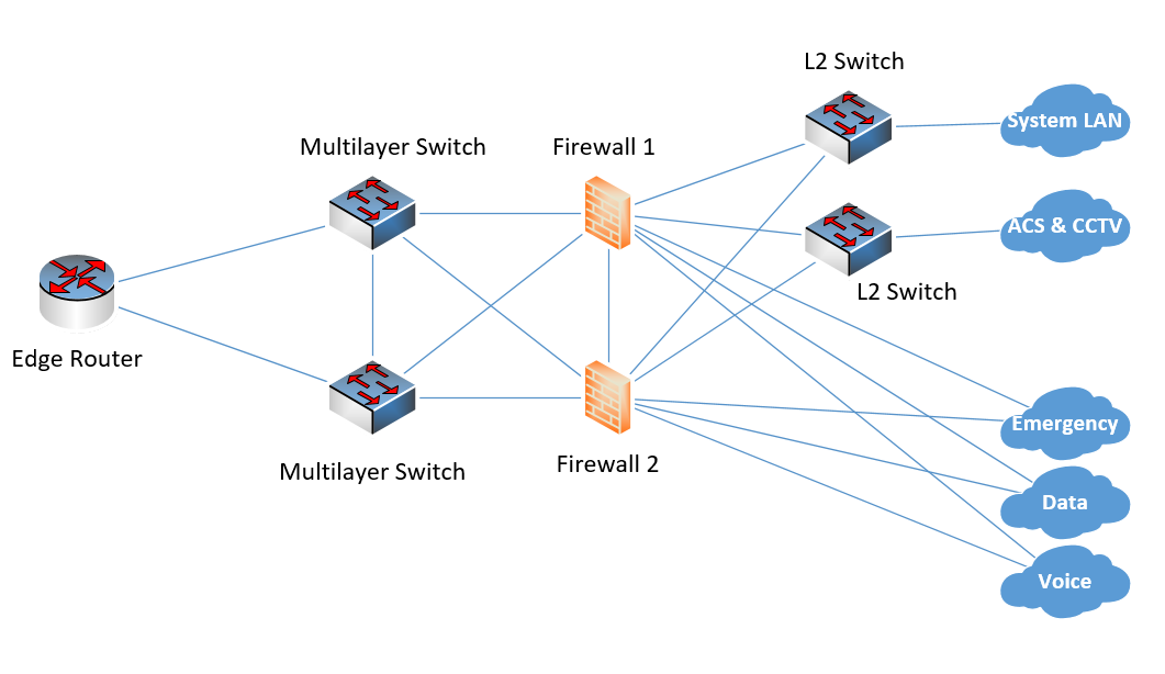
This way you can use the same two redundant firewalls to apply the policies, but the policies are applied to all internal VLANs. If you add more VLANs for which you want to apply security policies, you can do so by simply adding them to additional interfaces of the firewalls. Just be sure the firewalls have enough interfaces.
The other option is to use a virtual firewall such as the one I linked to in a previous post. This will give you more flexibility in configuring your policies. More info about such a firewall configuration can be found at the following lesson:
Just a note here, an NGFW is one that delivers capabilities beyond a traditional stateful firewall. A traditional firewall provides stateful inspection of incoming and outgoing traffic, typically up to Layer 4. An NGFW includes additional features like application awareness (up to Layer 7 of the OSI) integrated intrusion prevention and other features.
Typically all firewalls installed today for enterprise networks should be NGFWs unless only a very basic security level is required. So I would suggest an NGFW as the best and most secure option.
I hope this has been helpful!
Laz
Hello Szymon
If you limit a VLAN to a single access switch, then you can make the link between the two distribution switches an L3 link. You could still implement FHRP between the two distribution switches because any FHRP information exchanged between them would communicate via VLAN 10, that is, through the application layer switch itself. This enables you to keep FHRP, but it eliminates the need for STP (because there is no longer an L2 loop for VLAN 10) that would result in the blocking of one of the paths.
This means that both uplinks can be used simultaneously, making a more efficient implementation. In particular, the Nexus implementation of HSRP automatically load balances traffic in such cases, as does the VRRP and GLBP.
Does that make sense?
I hope this has been helpful!
Laz
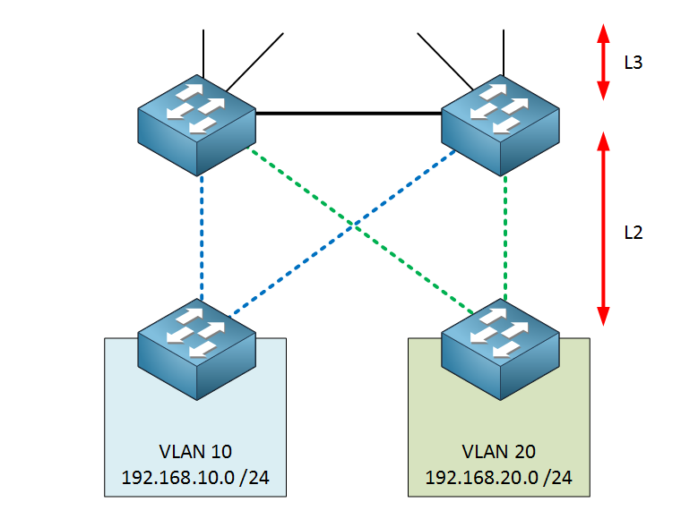
In this image the link between the Dist switches is Layer 3. My question is, how does the default gateway work here? Are we running an FHRP where the keepalives traverse the access layer switches? Thanks.
Hello Chris
In such a scenario you are still able to use an FHRP. The two SVIs in the distribution switches are on the same VLAN (green dotted lines and blue dotted lines respectively) and keepalives do indeed traverse the access layer switches.
I hope this has been helpful!
Laz
1 Like
Lazaros,
Thank you for the quick reply, your explanation has been very helpful. Does this design choice lend itself to spanning VLANs across the access layer? or is it better in this design choice to not span VLANs across the access layer switches?
Thanks so much.
Hello Chris
It is always considered best practice to limit the spanning of your VLANs to as few access switches as possible. This design allows you to do this, since, as you can see from the diagram in the lesson, the VLANs can indeed be confined to a single access switch.
Now this is an ideal situation, however, it is often the case where you need to span VLANs across multiple access switches, or even across multiple distribution switches, because your applications may demand it. So what do you do?
- Keep it to a minimum
- Where you cannot confine VLANs, try to keep the traffic on such VLANs to a minimum
- Where you cannot do that, make sure that there is enough bandwidth on the proper links to handle the traffic.
So you can see this is not a rule that must never be broken, but a rule that should be bent appropriately to minimize its impact on the network.
Ultimately the network is there to serve you and your applications. Make it work for you.
I hope this has been helpful!
Laz
1 Like
Lazaros,
Thank you. I did have another hypothetical scenario for you. Lets say we take the design above, where the connection between the Dist switches is a Layer 3 connection and the uplinks from the Access switches to the Dist switches are Layer 2. Now, lets say we span a single VLAN (VLAN 100) across BOTH access layer switches, what would be the result of that? Looking at it, i think this could be a disaster because a broadcast storm may loop endlessly in a “figure 8” pattern. Would STP even be able to block any interfaces for VLAN 100 in that scenario?
Thank you.
Hello Chris
Let’s take a look at it again:

In your description, both the green and blue dotted lines would be trunks, and both would carry VLAN 100, so you can have access ports on both switches on VLAN 100. That would indeed result in a layer 2 loop, however, STP would be able to stop it. That is the role of STP. If it is the figure 8 arrangement that concerns you, it’s the same thing as a square arrangement between all four switches. Just flip the access and distribution switches on the right (or left) and you’ll have four switches arranged in a square.
The result is that STP will indeed be able to block the appropriate port on VLAN 100, and avoid a loop. This is not ideal, as you would lose the benefit of the bandwidth of that blocked link, but it is doable.
I hope this has been helpful!
Laz
Hi,
In the cisco campus design network, how can we sizing the wright MTU in this kind of network.
Thanks.
Hello Willy
The sizing of the MTU is not something that is directly related to the Cisco campus network design philosophy. The MTU you will use depends primarily on the network services and features that are running on the network. For example, if you are running GRE tunnels through your network, or you are employing QinQ then you must adjust your MTU accordingly.
I hope this has been helpful!
Laz
Is this (why is this) an issue with just a single switch connected to a router. If there is a management vlan that requires routing, and that router has failed, wouldn’t an admin pc on connected to the data vlan of ANY of the switches (whether 1, 2, 3, or 100 switches) cause a communication failure to the management SVIs on all of the switches? Meaning, an admin PC would not be able to manage any of the switches.
Hello Laurel
In a larger topology with multiple switches, you will always have some backup for routing paths. You will typically have two (or more?) core routers that enable routing to all subnets within an enterprise. This means that even if one or more paths to the routing devices fails, or one of the routing devices fails, you still have some backup routing ability to get to the management VLAN.
The specific scenario described in the original post was a single switch connected to a single router, much like a router on a stick scenario. If the link or the router fails, the only way to gain access to the management VLAN is to directly connect a PC to a port that is configured on the management VLAN.
Remember, this is just a best practice guideline to avoid situations of loss of access to the management VLAN. For a single switch, the benefits of having a separate management VLAN are very few, compared to the difficulties such an arrangement may cause in case of a failure.
I hope this has been helpful!
Laz
1 Like
Hello, thanks for the class. I want to purchase the one-year access promotion.
I have some queries:
Communication between switch blocks has to go through the core layer, right? So assuming that if there is a VLAN with hosts located in different switch blocks, the links of the distribution and core switches have to be layer 2? is that possible?
-
Between the distribution layer and the core, do all the links perform mandatory routing?
-
Each link between the distribution layer and core, is a network segment with an address?
-
If layer 3 is executed in the access layer, would the routing be end-to-end (access layer to the core layer) and therefore all the links would be a network segment?
-
If I have 2 VLANs on different switch bloks, does their routing have to be through the core layer?
-
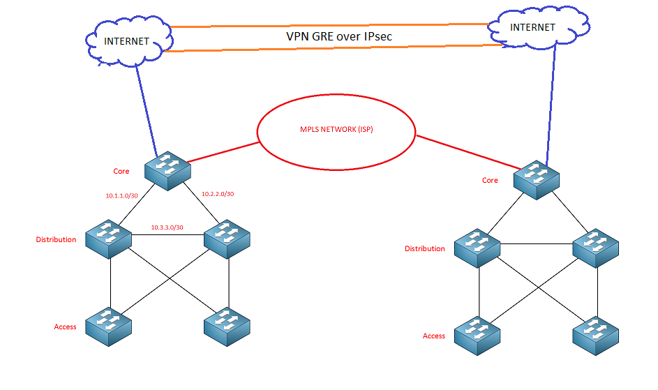
Will MPLS and Internet connections always be connected at the core layer?
-
If an enterprise has multiple campuses, then the core switches connect to the MPLS network and would they be the “Customer Edge (CE)”, running MPLS L3VPN or MPLS L2VPN (VPLS, VPWS)?
Could they also have a connection to the INTERNET (switches cores) and create tunnels? Then the cores exchange their campus subnets (VLANs) with the other cores through MPLS or VPNs?
Is what I say correct?
- Is it possible to have routers in the core layer or is multilayer switches better? Because
- This model only applies to campus networks, would that be the same as saying a main site (headquarters)? In the case of branches, are there any design considerations as well?
- I read in a Cisco guide that using VSS between the access and distribution layers avoids the use of STP and at the same time FHRP is no longer needed. However, the access and distribution layer enters, it is said to be layer 2. How would I apply the design there?