Hi Laz,
I also thought the same, that the switch port at 192.168.100.74 does not know where to respond to the ping.
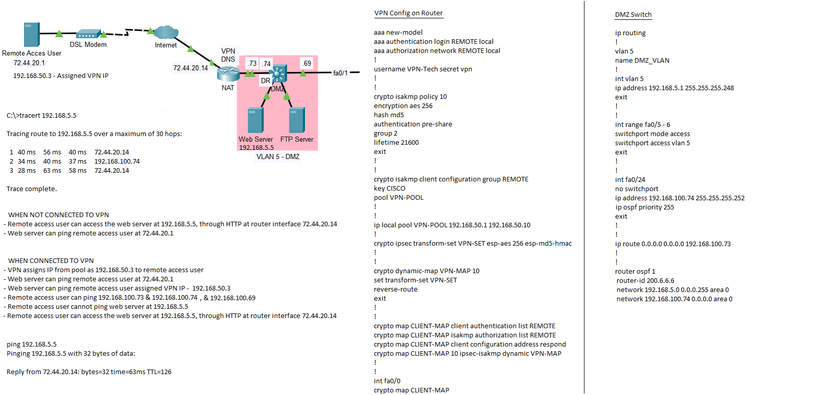
On the switch I have OSPF configured to advertise the route as:
network 192.168.5.0 0.0.0.255 area 0
network 192.168.100.74 0.0.0.0 area 0
OSPF is also configured on the VPN /NAT router to advertise the 192.168.100.73 0.0.0.0 area 0 network.
I also have a default route set on the switch: ip route 0.0.0.0 0.0.0.0 192.168.100.73
On the router I have 2 ACL’s configured but not applied to any interface:
Extended IP access list REMOTE-SITE-VPN-ACL
    10 permit icmp any any

Standard IP access list NAT-TRANSLATIONS
    10 permit 192.168.10.0 0.0.0.255
    20 permit 192.168.11.0 0.0.0.255
    30 permit 192.168.12.0 0.0.0.255
    40 permit 192.168.1.0 0.0.0.255
    50 permit 192.168.4.0 0.0.0.255
    60 permit 192.168.5.0 0.0.0.255

ip nat inside source list NAT-TRANSLATIONS interface FastEthernet0/0 overload
!
ip nat inside source static tcp 192.168.5.5 80 72.44.20.14 80
ip nat inside source static tcp 192.168.5.5 443 72.44.20.14 443
I am missing something, and I am not seeing what it is.
There are a couple of things that you should keep in mind as you troubleshoot this. First of all, with EasyVPN you don’t need to configure an ACL, so all traffic is permitted, so this is not where your problem lies. This is different than a site-to-site VPN where you configure an ACL to define the traffic to encrypt. It’s possible to use an ACL to restrict traffic with EasyVPN but you haven’t done this so you’re OK here.
Now you’re unable to ping from the VPN client to the web server, but you don’t know up to where the packet is going. Check to see how far the packet gets, to see if it actually reaches the web server and fails on the return, or if it never reaches it at all. Check all devices in between to see where the packet fails.
Finally, check your NAT rules. Specifically when you ping, check your translations and make sure that the address isn’t being translated in error before trying to be sent.
I hope this helps you in your troubleshooting, and points you in the right direction. Let us know how it goes!!
Hi Laz,
I am not sure if NAT Translation is affecting the connection.
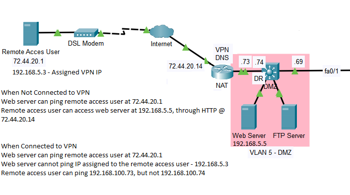
I had configured NAT translations for when you are trying to access the web server when not connected to the VPN, and not sure if its affecting the connection, so I changed the VPN pool to 192.168.50.1 192.168.50.10, then from the remote access user I can ping 192.168.100.74, and the web server can ping the remote access user @ 72.44.20.1, and the VPN assigned IP @ 192.168.50.3
The remote access user can’t ping the DMZ VLAN, VLAN 5 @ 192.168.5.1 on the switch.
Based on the tracert, if I am interpreting it correctly, from the remote access user the packet is going to the switch then back to the router.
If that’s the case then the switch is not forwarding the packet to the web server, unless I am mistaking it there.
ip local pool VPN-POOL 192.168.50.1 192.168.50.10
ip access-list standard NAT-TRANSLATIONS
permit 192.168.10.0 0.0.0.255
permit 192.168.11.0 0.0.0.255
permit 192.168.12.0 0.0.0.255
permit 192.168.1.0 0.0.0.255
permit 192.168.4.0 0.0.0.255
permit 192.168.5.0 0.0.0.255
!
ip nat inside source list NAT-TRANSLATIONS interface FastEthernet0/0 overload
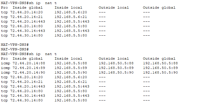
ip nat inside source static tcp 192.168.5.5 80 72.44.20.14 80
ip nat inside source static tcp 192.168.5.5 443 72.44.20.14 443
ip nat inside source static tcp 192.168.5.5 80 72.44.30.14 80
ip nat inside source static tcp 192.168.5.5 443 72.44.30.14 443
ip nat inside source static tcp 192.168.5.6 20 72.44.20.14 20
ip nat inside source static tcp 192.168.5.6 21 72.44.20.14 21
When connected to the VPN, I am not sure why the remote access user cannot ping 192.168.5.1 - VLAN 5 on the switch. OSPF is configured to advertise that network.
If NAT is affecting the connection, and I remove the NAT entry, then I am thinking I would not be able to access the web server when the VPN is not connected.
Without going into too much detail of this specific topology, let me give some examples and tools of how to troubleshoot a problem like this. Once you know how to deal with this, you can fix any topology. Like Lazaros mentioned, you should:
I’ll use this example topology. Four routers with EIGRP, full reachability:
Doing a trace is a good way to start. A single probe is fine:
R1#traceroute 4.4.4.4 probe 1
Type escape sequence to abort.
Tracing the route to 4.4.4.4
VRF info: (vrf in name/id, vrf out name/id)
  1 192.168.12.2 3 msec
  2 192.168.23.3 5 msec
  3 192.168.34.4 6 msec
In my case, I’m making it to R4 but If you see it stop somewhere, you’ll know which device to check first.
Check routing:
You can verify routing by checking the routing table or CEF. Check this on all routers in between the source and destination and for both the source and destination:
R2#show ip route 1.1.1.1
Routing entry for 1.1.1.1/32
  Known via "eigrp 1", distance 90, metric 130816, type internal
  Redistributing via eigrp 1
  Last update from 192.168.12.1 on GigabitEthernet0/1, 00:49:46 ago
  Routing Descriptor Blocks:
  * 192.168.12.1, from 192.168.12.1, 00:49:46 ago, via GigabitEthernet0/1
      Route metric is 130816, traffic share count is 1
      Total delay is 5010 microseconds, minimum bandwidth is 1000000 Kbit
      Reliability 255/255, minimum MTU 1500 bytes
      Loading 1/255, Hops 1
R2#show ip route 4.4.4.4
Routing entry for 4.4.4.4/32
  Known via "eigrp 1", distance 90, metric 131072, type internal
  Redistributing via eigrp 1
  Last update from 192.168.23.3 on GigabitEthernet0/2, 00:00:07 ago
  Routing Descriptor Blocks:
  * 192.168.23.3, from 192.168.23.3, 00:00:07 ago, via GigabitEthernet0/2
      Route metric is 131072, traffic share count is 1
      Total delay is 5020 microseconds, minimum bandwidth is 1000000 Kbit
      Reliability 255/255, minimum MTU 1500 bytes
      Loading 1/255, Hops 2
Or a CEF check is quicker:
R2#show ip cef 1.1.1.1
1.1.1.1/32
  nexthop 192.168.12.1 GigabitEthernet0/1
R2#show ip cef 4.4.4.4
4.4.4.4/32
  nexthop 192.168.23.3 GigabitEthernet0/2
Check packets:
If your packets are dropped, you’ll need to figure out whether a device forwarded or dropped a packet. On a router, you have multiple options. A very quick way is to check the outgoing packets on an interface:
That’s OK for a lab where you have a host connected to an interface without any other traffic, but otherwise not specific enough. If you want a detailed look, you could enable a debug or an access-list that permits everything but logs packets. For example, the debug:
R2(config)#access-list 100 permit ip host 1.1.1.1 host 4.4.4.4

R2#debug ip packet 100
IP packet debugging is on for access list 100
And here’s a “COUNTER” access-list:
R2(config)#ip access-list extended COUNTER
R2(config-ext-nacl)#permit ip any host 4.4.4.4 log
R2(config-ext-nacl)#permit ip any any

R2(config)#interface GigabitEthernet 0/2
R2(config-if)#ip access-group COUNTER out
If you only enable the debug on a router in between your source and destination (like R2) then you won’t see anything because the router uses CEF. Because of the ACL, you’ll see the debug messages because the router checks these packets.
Otherwise, you’ll have to disable CEF on the interface to see the debug. Do a quick ping from R1 to R4:
R1#ping 4.4.4.4 source 1.1.1.1 repeat 1
Type escape sequence to abort.
Sending 1, 100-byte ICMP Echos to 4.4.4.4, timeout is 2 seconds:
Packet sent with a source address of 1.1.1.1
!
Success rate is 100 percent (1/1), round-trip min/avg/max = 7/7/7 ms
Here’s the debug output:
R2#
IP: s=1.1.1.1 (GigabitEthernet0/1), d=4.4.4.4, len 100, input feature
    ICMP type=8, code=0, MCI Check(109), rtype 0, forus FALSE, sendself FALSE, mtu 0, fwdchk FALSE
FIBipv4-packet-proc: route packet from GigabitEthernet0/1 src 1.1.1.1 dst 4.4.4.4
FIBfwd-proc: packet routed by adj to GigabitEthernet0/2 192.168.23.3
FIBipv4-packet-proc: packet routing succeeded
IP: s=1.1.1.1 (GigabitEthernet0/1), d=4.4.4.4 (GigabitEthernet0/2), len 100, output feature
    ICMP type=8, code=0, Access List(52), rtype 1, forus FALSE, sendself FALSE, mtu 0, fwdchk FALSE
IP: s=1.1.1.1 (GigabitEthernet0/1), d=4.4.4.4 (GigabitEthernet0/2), g=192.168.23.3, len 100, forward
    ICMP type=8, code=0
IP: s=1.1.1.1 (GigabitEthernet0/1), d=4.4.4.4 (GigabitEthernet0/2), len 100, sending full packet
    ICMP type=8, code=0
This gives me a detailed output of what is going on with the packet. Here’s the access-list output:
R2#show logging | include COUNTER
*May 14 17:45:36.007: %SEC-6-IPACCESSLOGDP: list COUNTER permitted icmp 1.1.1.1 -> 4.4.4.4 (0/0), 1 packet
In the access-lists I used, I only check the traffic from the source to the destination. You can also add a permit statement for the traffic from 4.4.4.4 > 1.1.1.1 to see the return traffic. These two options help to figure out what a router is doing with your packet.
NAT Debug:
Any “services” like NAT, PBR, QoS, access-lists, etc. can mess up your packets or traffic patterns. You can use a bunch of show commands but a debug gives you an insight what the router is doing. We don’t have NAT right now but let me enable it on R3 for traffic from 1.1.1.1 > 4.4.4.4:
R1#ping 4.4.4.4 source 1.1.1.1 repeat 1
Type escape sequence to abort.
Sending 1, 100-byte ICMP Echos to 4.4.4.4, timeout is 2 seconds:
Packet sent with a source address of 1.1.1.1
!
Success rate is 100 percent (1/1), round-trip min/avg/max = 13/13/13 ms
Here’s the NAT table:
R3#show ip nat translations
Pro Inside global      Inside local       Outside local      Outside global
icmp 192.168.34.3:18   1.1.1.1:18         4.4.4.4:18         4.4.4.4:18
That’s nice for a small lab but in a production network, you’ll see dozens of translations. You can debug NAT as well:
R3(config)#access-list 1 permit host 4.4.4.4

R3#debug ip nat 1
IP NAT debugging is on for access list 1
Now do another ping:
R1#ping 4.4.4.4 source 1.1.1.1 repeat 1
Type escape sequence to abort.
Sending 1, 100-byte ICMP Echos to 4.4.4.4, timeout is 2 seconds:
Packet sent with a source address of 1.1.1.1
!
Success rate is 100 percent (1/1), round-trip min/avg/max = 13/13/13 ms
Hi Rene,
Thanks for your advice. I tried some of the stuffs but I am still not getting it to work. I have a fracture and using some medications that’s causing me to be woozy. Have to see the orthopedic doctor in the morning. Maybe I will skip this topic and move on. I have about 3 general questions more to resolve for now, on ACL, OSPF Summarization, & Assigning management VLAN, but once again thank you
If the vpn router is behind another router so not direct on the public network can I use the public IP address of the edge router and use port forwarding?
Yes, it is possible to have the EasyVPN configuration traverse the NAT router. In order to do this, you must enable the NAT-Traversal feature on the VPN router and to appropriately set up PAT on the edge router. More detailed information about this feature can be found here at this Cisco community thread: