This topic is to discuss the following lesson:
You say for the destination you have to specify the source IP address, but I don’t see that anywhere in the config?
Also is the GRE tunnel between the wireshark server and R1, rather than R1 and R2?
Thanks
Hello Chris.
Yes, you are correct. @ReneMolenaar states that:
For the destination we have to specify:
…
- Source IP address: has to match with the origin IP address of the source session.
It should read:
- Source IP address, which is the same as the destination IP address of the corresponding source session
as stated in Cisco Documentaiton.
So, the Source IP address stated should be the IP address of the Wireshark PC as shown in the last line of Rene’s configuration:

I will let @ReneMolenaar know to update it.
As for the GRE tunnel, that exists only between the two routers, specifically, between the two Gi3 interfaces. Note that packets captured by the Wireshark PC do not include any of the GRE headers as these are stripped before being passed on.
I hope this has been helpful!
Laz
The Wireshark capture in the lesson shows the GRE encapsulation.
Hello Micah
Yes I stand corrected, the GRE header is included as the tunnel used by ERSPAN.
Thanks!
Laz
There is also a slightly different way to configure the “sniffer” as a layer 2 device.
Many sniffers will not use a layer 3 IP address on the network to sniff traffic, they will have an IP for management, but layer 2 interfaces with no IP for capturing network traffic.
In this case you can configure the source and destination IP as a loopback on the remote router, and the destination interface as the layer 2 interface of the sniffer. In this case, the GRE header would surely be stripped on the router.
You can also combine RSPAN and ERSPAN. For example it’s possible to create a rspan vlan and then use this vlan as source for the ERSPAN session. Later you can cut off the GRE Header to get the original frame:
editcap -C 50 capture.pcap caputure_filtered.pcap
1 Like
Hi Rene,
I am still lost here.
R2(config)#monitor session 1 type erspan-destination
R2(config-mon-erspan-dst)#no shutdown
R2(config-mon-erspan-dst)#destination interface GigabitEthernet 2
R2(config-mon-erspan-dst)#source
R2(config-mon-erspan-dst-src)#erspan-id 100
R2(config-mon-erspan-dst-src)#ip address 172.16.2.200
Looking at the configuration above. I do not know how R1 sees 172.16.2.200 as the destination IP address and R2 sees same IP address as the source IP address.
I thought the source IP address from R2’s perspective should be the 172.16.12.1, IP address of R1.
secondly, you are using the tunnel source interfaces and not the tunnel interfaces in the configurations. right?
Thank you for always helping.
1 Like
Hello Ayong
It seems there may be a typo in the configuration. The GRE tunnel must terminate on the routers, and in order to do so, the following must be true:
For the configuration in the source device, the IP address command should have the destination IP where the tunnel will terminate on the other device, namely 172.16.12.2. The destination device, should have the same address configured for its ip address command, namely 172.16.12.2. In both cases, the IP address configured was that of the wireshark device, which is incorrect. I will let @ReneMolenaar know to make the correction.
Yes, that is correct. We are not actually explicitly creating tunnel interfaces, that is being done by the mechanism itself, so we must reference the physical interfaces.
I hope this has been helpful!
Laz
2 Likes
Thank you Lazaros,
That makes it clear
Hye Rene and Laz,
I can’t understane why we need to configure the source IP of the wireshark server in R2 , how its going to make the ERSPAN work?
You are stating it should match the origin IP of the source, but instead you configured it to match for the destination IP that was configured on the source.
Hi,
Is your reply about the correction still true because I also thought the same - i.e. the 172.16.12.2 should be used, not the Wireshark IP (172.16.2.200)? However, I have read other text and it also uses use the monitoring node’s IP not the switch/router IP.
Thanks,
Sam
1 Like
Hello Samir
The truth is that the Cisco documentation that describes this configuration is not quite clear. In this Cisco Documentation, it states that the destination IP simply:
Configures the IP address that is used as the destination of the ERSPAN traffic.
However, examining other example topologies, it seems to confirm that the destination IP is indeed the GRE tunnel destination.
Remember that this configuration creates a special GRE tunnel to transport all of the captured packets, and a tunnel destination is necessary.
The only way to determine for sure the correct configuration is to try it out for yourself. If you do so, let us know your results!
I hope this has been helpful!
Laz
1 Like
Hi Lazaros,
Yes, I’ll try when I have time (cramming for ENCOR so wont be soon). Although I suspect both ways work.
Maybe with the destination IP as the router, the GRE is de-encapsulated before being forwarded to sniffer, but with sniffer IP set as the destination address, the traffic bypasses the router where the GRE tunnel is supposed to be de-encapsulated. That should mean ERSPAN would still worked with just the source end of the GRE tunnel configured (because traffic is all one way anyway), but that’s just a guess.
Thanks,
Sam
Hello Samir
I wish you success in your ENCOR exam! If you need anything let us know. As for the ERSPAN, when you do look into it let us know your results. Your thoughts here make sense, although it is still hard to imagine the use of the Wireshark device IP as the other end of the tunnel. In any case, a practical test will resolve any doubts.
Laz
Hi Laz,
Thanks very much!
Sam
1 Like
Hello,
I am wondering if it is possible to make a loop in the network using ERSPAN.
Consider the following scenario :
I have two routers, router A and router B. There is one monitoring node connected to router A, and there is an ERSPAN session from router B to router A to copy traffic of specific vlans (let’s say vlan 100). Then router A sends that traffic to the monitoring node.
What if I add a new monitoring node, but this time connected to router B. I create a new ERSPAN session, now from router A to router B, to copy traffic of the same vlans (vlan 100).
What I am wondering is whether or not that could create a loop ? i.e., router B receives traffic on vlan 100 and copies it to router A via its ERSPAN session. And then, after receiving this, router A notices that it’s vlan 100 so it’s going to also copy that traffic back to router B via the new ERSPAN session I configured. Is it possible ? Or would it only be the “true” vlan traffic entering the Nexus devices that get copied by the ERSPAN session ?
I made a quick drawing to try and make it more clear:
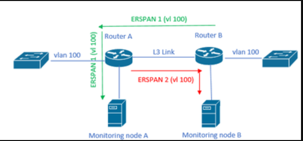
So basically: would a loop be created between those 2 ERSPAN sessions ?
Hello Halouoi
This would not create a loop simply because the ERSPAN traffic is not part of VLAN 100. ERSPAN traffic is encapsulated within GRE tunnels, so it does not register on any VLAN. That means that each ERSPAN session will capture traffic on VLAN 100, but this will simply not include the already “captured” traffic within the GRE tunnel, so no loop would be created.
I hope this has been helpful!
Laz
Hello team,
I was wondering if there is a typo at the beginning of 1. :
“Above we have two routers, R1 and R2. On the left side there’s a host (H1) and on the right side, I have a machine running Wireshark. I will show you how to capture traffic on the Gigabit 2 interface of R2 and send it towards the Wireshark machine behind R2.”
We’re capturing traffic on the Gigabit 2 interface of R1 right?
Thanks,
1 Like
Hello David
Yes, you are correct, thanks for pointing that out. I will let Rene know to make the correction.
Laz