Remember that HSRP provides gateway redundancy by allowing multiple default gateways to operate as backups for each other for the hosts they serve. If those default gateways happen to be SVI interfaces on a Layer 3 switch, then yes, you must create the VLANs and the corresponding SVIs to serve those hosts. In such a case, the HSRP configuration would take place on the interface configuration mode of the SVIs that belong to those VLANs.
If, however, you are applying HSRP to gateways that are actually routed ports on a router, then you don’t need to create those VLANs. It all depends upon your network architecture.
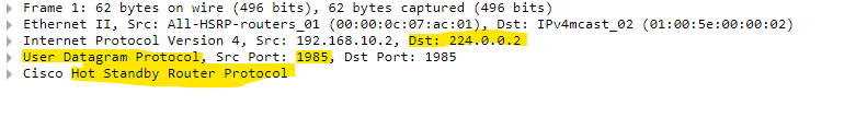
For HSRP, the hello packets are sent as multicast. Specifically, HSRP routers send hello messages to the multicast address 224.0.0.2 on UDP port 1985 to ensure the availability of the HSRP peers.
Take a look at this cloudshark capture of an HSRP hello packet:
When first attempting this lab I tried to use vlan 10 SVI instead of vlan 1. Was running into issues with the two switches not being able to communicate. I had establish trunk between the two HSRP switches in order to establish communication for both vlans. Wanted to post this In case anyone is trying this and isn’t using the default vlan.
In your topology you have an unmanaged switch that connects the two PCs. By definition, this switch cannot “understand” VLANs. It considers all devices connected to it on the same VLAN. I also see that you have the 192.168.1.0/24 subnet assigned to both PCs, however, you indicate that the PCs are in different VLANs. If you want to create multiple VLANs, you must create a separate IP subnet for each VLAN, as well as a separate HSRP instance for each SVI of each VLAN you want to use. With this in mind, and assuming you want to apply two VLANs (one for each PC):
The first thing I would do is change the unmanaged switch to a managed switch and configure the appropriate VLANs on that. Let’s call that newly managed switch SW3. You should also ensure that the ports that the PCs are connected to are configured on the correct VLANs.
Secondly, create two subnets, one for each VLAN, and ensure that the IP address ranges correspond with those you have assigned to each VLAN.
Thirdly, you should ensure that your connections from SW3 to SW1 and SW2 are trunks, and include both VLANs 10 and 20. Third, make sure that the trunk between SW1 and SW2 also includes VLANs 10 and 20. This is not strictly needed, because the switches should be able to communicate HSRP information via the trunks to SW3, however it is best practice.
Finally, you should ensure that your HSRP configuration for your SVIs of 10 and 20 is functioning correctly using the show commands indicated in the lesson. Remember, in order to have each PC communicate with the redundant default gateways of its VLAN, each SVI for each VLAN must be configured for HSRP on both switches.
Let us know if any of this helps you out, and if you have any further questions feel free to let us know!
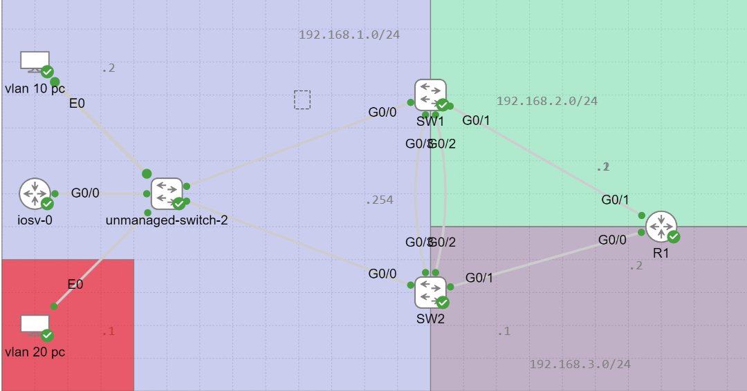
Thank you the insight on the necessary changes. I’ve been really trying to understand best design practices. I do have another question. I have this topology here
I’ve redone this lab with the suggestions you’ve made. Access switches have been configured and PC’s have been assigned the correct vlans. The links to the distro switches are all trunks with the appropriate allowed vlans. I’ve ensured all vlans exist on the switches. To me it seems inter-vlan routing should work. Here’s the route table from on of the distro switches.
      192.168.1.0/24 is variably subnetted, 2 subnets, 2 masks
C        192.168.1.0/24 is directly connected, Vlan20
L        192.168.1.254/32 is directly connected, Vlan20
      192.168.2.0/24 is variably subnetted, 2 subnets, 2 masks
C        192.168.2.0/24 is directly connected, Vlan10
L        192.168.2.254/32 is directly connected, Vlan10
Vrrp has been configured between the two vlan 10 interfaces on both the distro switches(same thing for vlan 20 interfaces).
I can ping the other vlan 20 pc but not the vlan 10 pc. I can also ping the gateways on the perspective devices. No need to dig to deep into this but is there anything at a initial glance that comes to mind?
At first glance, it looks good. In this post, you mention VRRP while in the previous it was HSRP. Whether that was a typo or it really is the case, the topology and the logic behind it remain the same. I will assume you’re using HSRP.
To ensure that your HSRP configuration is correct, use the corresponding show commands. For HSRP use the show standby and the show standby brief commands. Next, make sure you can ping the virtual IP that corresponds to the default gateway from the PCs (and make sure the PC’s default gateway is configured to the virtual IP for each subnet). Based on what you’ve said, it looks like you’ve done this.
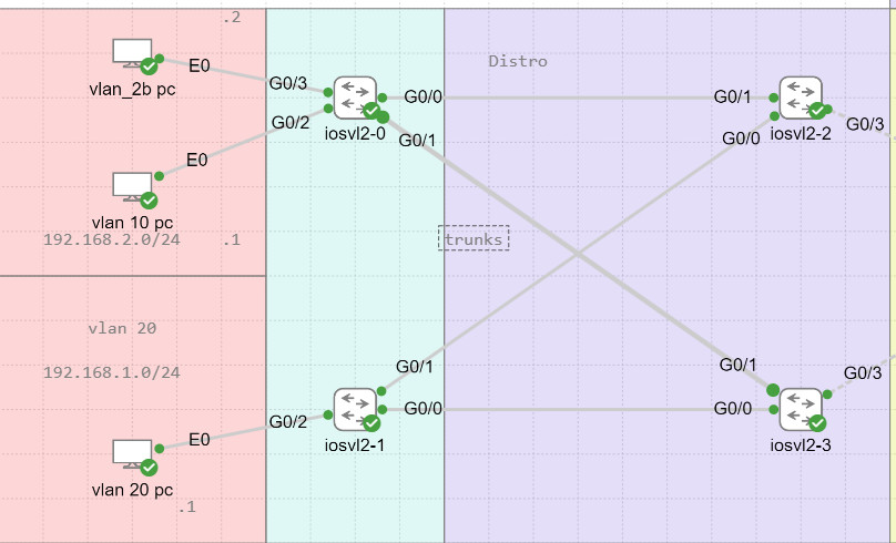
Once that connectivity has been ensured, you can then check for inter-VLAN routing. Switches iosvl2-0 and iosvl2-1 must be functioning at layer 2. The inter-VLAN routing will take place within the two distro switches. Based on your routing table, it looks like it should work.
Where are you pinging from? I assume from one VLAN 10 PC to the other, and then to the VLAN 20 PC where it fails. The only other thing I can think of is on the distro switches, the SVIs may be down for some reason. Sometimes the SVI may be down if there are no access ports assigned to it. Take a look at this NetworkLessons note on the topic of SVI status for more info. (but you did ping the gateways from the PCs so that’s probably not it… )
Also, ideally, you should have a link between the two distro switches as a trunk allowing all VLANs. Even though HSRP communication can take place via the trunk links with the -0 and the -1 switches, it is preferable to have a direct link. This should not affect the result of your topology but is just a best-practice approach.
As you troubleshoot, if you are still having difficulty, feel free to share more information about your topology with us so we can help you out further.
Hi,
am I wrong to say that the track interface feature is relevant only if static routes are configured? When dynamic routing is configured between L3 switches and R3 and SW2 uplink fails, SW2 is able to find alternative path to R3. SW2 informs H1 via ICMP redirect about alternative path and traffic flows via SW1 despite HSRP on SW1 is in standby state? Thanks
However this is not quite correct. The ICMP redirect introduces a bit of confusion in this case, since it is typically used when the default gateways have different IP addresses such as in this lesson. In the case of HSRP, the same virtual IP address is used, so an ICMP redirect will not resolve the issue.
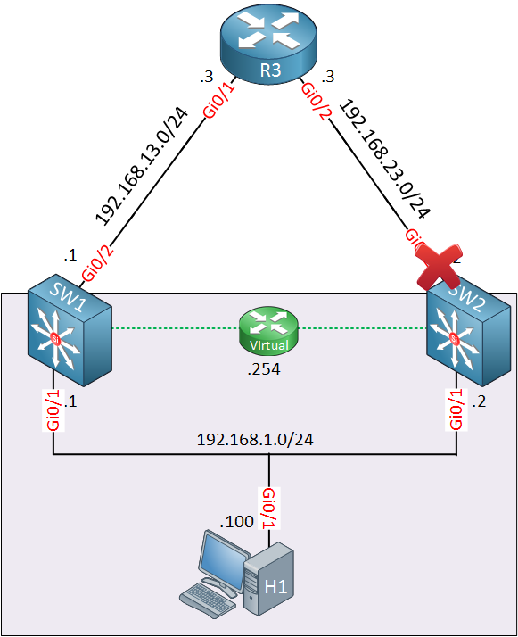
The functioning of HSRP is distinct from the operation of routing. The purpose of the tracking function here is to affect which of the HSRP members adopts the virtual IP address of the default gateway of the subnet. So no routing is actually changing here, even if tracking does change. Take a look again at the following diagram:
Tracking will cause SW1 to adopt the virtual IP address of 192.168.1.254 of the subnet. The H1 device is oblivious to this process as it still has the same default gateway IP address.
Now what happens beyond SW1 and SW2 and their connection with R3 and how routing is established is not directly affected by the tracking feature. It is indirectly affected because of the failed link of course, but not directly by the tracking feature itself. Does that make sense?
When configuring HSRP, how can I access the Standby IP? My management IP is configured with HSRP with R1=x.x.x.2 (PRI) & R2=x.x.x.3(Sec) with Virtual IP of x.x.x.1 with R1 been Active and R2 been standby.
Is there a way to access the standby router from a Management perspective?
HSRP creates a virtual IP address that is shared between two or more default gateways. That IP address is adopted by the primary gateway, and can be automatically adopted by the standby device(s) if the primary device fails.
This mechanism does not prevent you from accessing the individual devices using their “real” IP addresses, that is, the IP addresses assigned to the physical router interfaces, or SVIs that are being used by each device. So you should be able to access R1 by using its x.x.x.2 address, and R2 by using its x.x.x.3 address without any problem. Does that make sense?
Understood, but i am not able to access the Standby Router, I cannot ping it. when doing sh standby brief, i can see the active and Standby, I can Ping the Virtual IP and the active IP but not the Standby IP… Am I doing something wrong?
You must approach this problem as being independent from HSRP. You simply want to achieve connectivity to the x.x.x.3 address which is R2.
Now if you can ping the IP address of R1 (the active IP) then that means that you have established routing from the source of your ping to the destination network (i.e. the network to which both R1 and R2 belong). Since you are not getting a response from R2 (x.x.x.3), then the first step I would take is to examine the configuration on R2. Check that the interface is up, with the correct IP and subnet mask, and more importantly, that routing has been configured on R2 so that the ping it receives can be responded to with an echo reply that will successfully be routed back to the source.
If you’re still having problems, give us some more information about your topology and configurations so that we can help you troubleshoot further.
I just lil bit confused in HSRP configuration actually i am stuck in switch port and routed port on Multilayer Switch and to know where we configure HSRP and how we can decided it .
Is there any way to understand this topic in better way or in linean term as configuration was very tough i believe .
Can you share what config was running on multilayer switch & why ip routing command not enabled on this multilayer switch can you share some insight over this ?
HSRP is always applied to a Layer 3 interface, and cannot be applied to a Layer 2 interface on a switch.
When we talk about routers, all configurations are applied to the physical interfaces themselves since they are always Layer 3 interfaces.
For multi-layer switches however, you can apply HSRP on a routed port, or on an SVI because both are Layer 3 ports.
Now the tricky part I think is, within a topology, how do you know which Layer 3 ports to apply the commands to? The key is this: The Layer 3 ports that will play the role of the redundant default gateways must be in the same subnet/network segment/broadcast domain.
So for two Multilayer switches that are connected to each other with a trunk, you would apply the HSRP configs on the SVIs of the same VLAN. If you are applying this to routed ports, then those routed ports must be connected to the same subnet. This would typically be done with an additional Layer 2 switch to which those routed ports connect.
In order for HSRP to function, the switch being used must function at Layer 3, and for this reason, the ip routing command must be enabled if you are using a multi-layer switch. However, in the lesson, this was not done. This could be because the specific model used by Rene has routing enabled by default, or because he simply considered it self-explanatory… In any case, the config in the lesson is indeed running multi-layer switches.
This one is not clear , can you please help over this on command level i believe it not required if there are in same vlan , concept of SVI is for inter vlan but why you imphasis more in same vlan here
Can you explain how it can be happend , what i know inter vlan routing will work when the host are in different Vlan .By default it on vlan 1 if we talk about routed port i did not get this statement properly .
inter-VLAN routing is needed for communication between the subnet of that particular routed port, and VLANs on the switch
Let me try to clarify. If we are talking about HSRP where two routers play the role of the redundant gateway, then the interfaces of the routers that are acting as the redundant gateways must be in the same subnet. This can be seen in this diagram here:
The Gi0/2 interfaces of C1 and C2 must be in the same subnet/network segment. In other words, a Layer 2 infrastructure must connect them. Why? There are two reasons:
A gateway is used to reach networks outside of the local subnet. The interfaces that act as the redundant default gateways must both be in the local subnet for which they will act as gateways.
The second reason is that HSRP requires that these interfaces communicate directly with each other to exchange HSPR messages. This exchange takes place over the same Layer 2 connection between them.
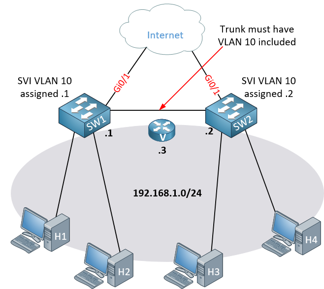
Now how are these principles applied when we have L3 switches with SVIs? Take a look at this topology:
Here we have SW1 and SW2 and each one has an SVI of VLAN 10 assigned to the 192.168.1.0/24 network, just like the routed ports. In order to ensure that the SVIs can communicate with each other to exchange HSRP messages, we must have the same prerequisites as before. The SVIs must have the same VLAN SVI on each switch, they must be on the same subnet, and they must be able to communicate with each other at Layer 2. The only way they can do this in the above topology is if they have a trunk link between them that includes VLAN 10.
With such a topology, the trunk between the switches also acts as a path for the hosts to reach either default gateway.
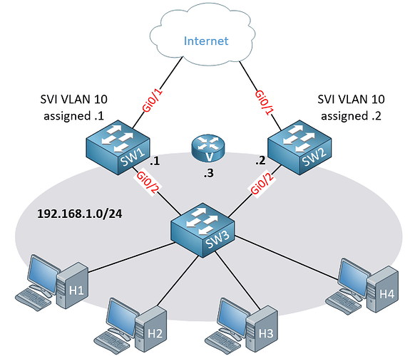
In this topology, you don’t need a trunk between SW1 and SW2 because the SVIs can communicate with each other (for HSRP) via SW3. But this adds an additional device in the communication path between SW1 and SW2.
Ideally, you should create a trunk between the L3 switches that includes the VLAN for which the SVIs have been configured with HSRP, regardless of what other infrastructure you place between the L3 switches and the hosts that are served by those redundant SVIs.
Hope you are doing well , Is there any need to add port in vlan like in 2 and 3 topology b/w L3 switch - - Host & multilayer switch L3 —L2 Switch interface , shall I configure access port to add port in specific vlan 10 on both end interface side ?
Is it compulsory to add port in vlan while configuring SVI on Multilayer switch ??
In both the second and third topologies that I have in my post, VLAN 10 must exist on some link or path between the two L3 switches. Either through trunk links, as is the case in the 2nd topology, or through access links using VLAN 10. For example, in this topology:
The links between SW1-SW3 and SW2-SW3 can be access ports on VLAN 10, or they can be trunk ports that include VLAN 10.
When you configure an SVI, in order for that SVI to enter an “up” state, you must have that VLAN assigned to either an access port that is up, or to a trunk port that is up. For more information, take a look at this NetworkLessons note on the topic.
Question about the default timers (hello = 3 sec and hold = 10 sec). I am running a similar setup to the topology shown in this lesson on CML, with the default timers, but when I shut down the active routers interface the standby router takes over within 1 second as opposed to waiting for 10 seconds like the lesson says. I did confirm the hello and hold timers are indeed 3 and 10 by issuing the show standby command on both routers. Shouldnt there be 10 seconds before the standby router becomes the active one?
I read about HSRP resign packets being sent in the case that we shut down an interface on purpose to speed up the standby routers transition into the active role. I did a wireshark capture on CML and i did see the resign packets. So if we purposely shut down an interface, the HSRP resign packets would allow the standby to take over way before the hold timer expires?