Hello Rene,
thanks for your interesting lesson, as always, I like your way to explain and clarify things.
I wonder, if I can reach my following goal with HSRP. I have a HSRP group running. Both routers have each a running upstream and downstream OSPF connection to 2 different routers . What I need to reach is that only the active router takes part in OSPF, the standby must not participate in OSPF at all, as long as it’s becoming active. I don’t want the standby router to show up in the neighbor table of the other OSPF speakers. Adapting OSPF costs does not get me any further…
Thanks for your time!
Remember that HSRP is primarily used as a method for achieving gateway redundancy for end devices such as PCs, IP phones, IP cameras, printers etc… This means that the redundancy group that is created on a pair of Layer 3 devices using HSRP should be facing a subnet with such end-user devices.
Now based on your description, you are trying to use HSRP to provide gateway redundancy to OSPF routers, correct? Now, this can be done, however, it is not the most elegant solution. This is because typically, the virtual IP created via HSRP cannot participate in OSPF (or any routing protocol for that matter). Only the “real” addresses can participate. This presents a problem when attempting to achieve redundancy.
In general, if you want to achieve such redundancy, you should use the load balancing and rerouting capabilities of the routing protocol itself rather than relying on HSRP. However, can you let us know a little bit more about what you want to achieve, and why you want only the active router to participate in OSPF and not the standby router? Maybe we can suggest another solution for your requirements.
Thanks a lot for your reply.
My generell goal to achieve is to create a copy of our production environment in GNS3. I want to represent a firewall cluster here. As the real firewall cluster would gobble up huge amounts of resources within GNS3, my idee was to replace it with 2 HSRP routers as the firewall rule set would not be needed in GNS3. The firewall cluster provides local redundancy as well as represents itself as a single OSPF speaker to others, meaning if the firewall master goes down, the slave takes over (just like HSRP) and only the slave (new master) talks OSPF withe the SAME ROUTER ID that the former master used… Always only one OSPF Router (firewall) can be seen from the perspective of the other speakers…
But as I learned now, this will hardly to be achieved by using a HSRP pair…
Ah, I understand. Yes, HSRP is not a good choice to “simulate” the redundancy provided by a firewall cluster, and you can’t achieve what you need in this way. How large is the firewall cluster you want to create? It may be worth taking a look at the GNS3 forum to see how others have achieved such simulations…
I thought it should only be configured on the master HSRP so if it reloads (for whatever reason) it doesnt assume the master/active role immediately so to allow in your words “OSPF or EIGRP need to form neighbor adjacencies or spanning-tree isn’t ready yet unblocking ports,” if need be.
You can issue this command on both devices if you wish, however, it will only really have meaning if you configure it on the device that has the higher priority. What preempt does is this:
If both devices are up, and the device with the higher priority is not active, it preemptively becomes active.
There will never be a case where both devices are up, and the device with the lower priority will preemptively take control. So you may configure it on the device with a lower priority, but for that device, the preemptive conditions will never occur. Since preemption will never take place, the delay parameter is also moot.
Hi,
I understand the whole HSRP process and use it daily but I have recently came across an unusual setup.
If I have a pair of switches running hsrp and have 10 SVI’s running hsrp I assume best practice would be to create a unique hsrp group number for each SVI running hsrp.
For example -
Interface vlan 1
standby 1 ip x.x.x.x
interface vlan 2
standby 2 ip x.x.x.x
interface vlan 3
standby 3 ip x.x.x.x
interface vlan 4
standby 4 ip x.x.x.x
etc…
I know the standby numbers dont need to match the vlans and I understand that the virtual mac will be 0000.0c07.acxx with the xx being the group number in hex.
But I have recently came across a setup where there are a pair of switches running hrsp that have approx 10 vlans with SVI’s running hsrp as gateways for their downstream devices.
Nothing strange there but what is strange is that the hsrp group numbers are configured with all the same number.
So under every single SVI the standby group is “1”.
For example it looks like this -
Interface vlan 1
standby 1 ip x.x.x.x
interface vlan 2
standby 1 ip x.x.x.x
interface vlan 3
standby 1 ip x.x.x.x
interface vlan 4
standby 1 ip x.x.x.x
that obviously gives the same virtual mac address to every downstream device in each subnet - 0000.0c07.ac01
It seems to be working fine and have though about this and I assume as the traffic in the frame would be going to the correct location and then de-encapsulated to get the correct IP and then forward the traffic as normal then thats how this appears to be working fine or am I missing here ?
Is this an accident waiting to happen ? What exactly could go wrong here if anything or is it ok to use the same hsrp standby number for each vlan SVI ?
That’s a very interesting situation. I’ve never come across this, but it’s a very interesting thought experiment. Actually, in most modern switches, it turns out that using the same standby number for multiple SVIs doesn’t affect the operation of HSRP at all.
Remember that if you have two L3 switches connected to each other, and they are operating as HSRP pairs making their SVIs redundant gateways for their respective subnets, then each redundant pairing operates within its own discrete Layer 2 domain. And since all HSRP communication for setting up the redundancy is confined to that layer 2 domain, there are no issues with duplicate standby numbers.
This does not cause a problem with the MAC addresses either. Even though the same MAC-address is going to be returned in an ARP response for every group that uses the same group number, because the ARP query and response are bound by the L2 broadcast domain of the vlan.
Now some older switches choose to maintain a system-wide MAC address table regardless of VLAN, and in such a case, you will experience problems. Also, if two VLANs/subnets are connected at Layer 2 by accident or on purpose, using the same standby group number, and thus the same MAC will cause problems.
Even so, best practice dictates that you should use different standby numbers if only to keep everything tidy and comprehensible. Using the same standby numbers may lead to more human error in configuration than anything else.
Some Cisco community threads that may shed some more light on this for you are shown below:
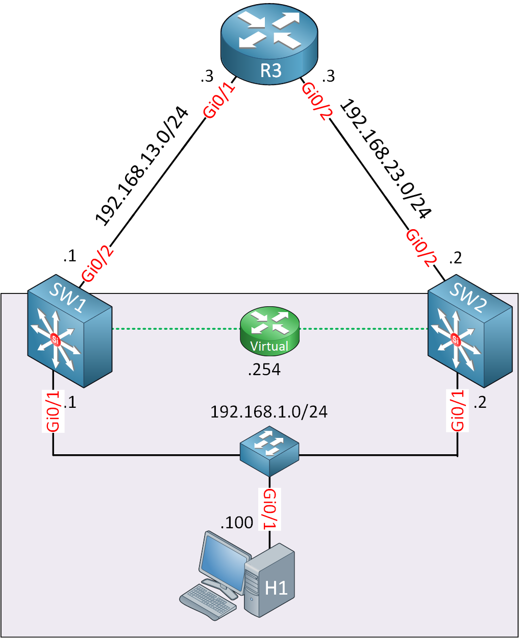
Thanks for the extra explanation on the preemption delay. Could you give an example where a router would not have a complete routing table? In the lesson diagram with SW1, SW2 and R3, there is no reason for SW2 not having the routing table if we are using, for example, OSPF?
I’m not quite sure what you mean, but I’ll do my best to explain HSRP and its functionality with OSPF and other routing protocols.
Using HSRP with a routing protocol such as OSPF for example, can sometimes be tricky. It’s important to realize that HSRP and other FHRPs typically deliver a default gateway to subnets that contain end user hosts. So the actual virtual gateway that is created should only be facing the subnet where the end users are. Those end users should be using that virtual gateway as their default gateway.
Any routing protocols that HSRP devices participate in should take place on other interfaces and not those of the virtual router.
In other words, the virtual default gateway and the SVIs or routed interfaces associated with it should not be used to create OSPF neighbor adjacencies.
Indeed, those interfaces should ideally be configured as passive interfaces for the routing protocol being used.
Now, having said that, OSPF can be initiated between R3 and the two switches so that the 192.168.1.0/24 network will be advertised to R3. That network would be advertised by both SW1 and SW2 to SW3, and
As it is now, R3 cannot reach that subnet, but that was not necessary for the needs of the lesson.
Does that make sense?
My question was about this sentence:
“By default preemption will take effect immediately but it might be a good idea to use a delay. If a router or reboots it might need some time to “converge”. Maybe OSPF or EIGRP need to form neighbor adjacencies or spanning-tree isn’t ready yet unblocking ports.”
Would you have an example of an issue caused by preemption taking effect immediately while convergence is taking place?
even whn i change the active rtr the same, i cannot ping the 13.3.
Any suggestion?
more questions ti understand.. the docs does not mentions that SW2 forward the packets to SW3 when all the interfaces are up, SW2 is the active SW2, SW3 is the standby and ping from pc to 23.0 network. Is that right? If yes SW2 does not know anything for 23.0 on its routing table. Should i add sthing on it?
I am tyrning the interface on g2/0 down. SW2 still active, can SW2 route to 23.0 network?
Next SW2’s f0/1 interface goes down, SW3 becomes after delay active, can it route packets to 13.0? How since it does not know anything for this network?
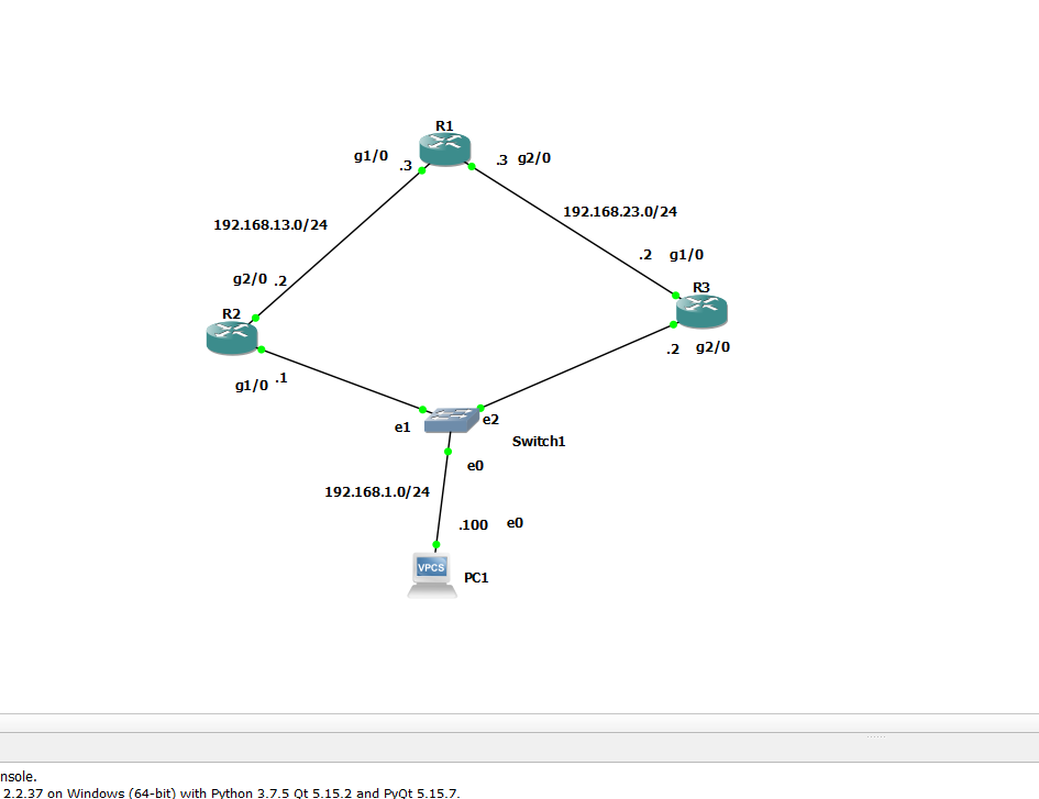
Thanks for the clarification. Let’s take a look at the diagram from the lesson once again and look at a couple of best practices that should be employed with HSRP and routing protocols. Then we’ll take a look at the problems that preemption can cause:
Now imagine that OSPF is configured between SW1, SW2, and R3. If you leave OSPF configurations at their defaults, R3 will load balance traffic destined for the 192.168.1.0/24 network across both SW2 and SW3. Ideally, we want OSPF to forward traffic to the active HSRP device for that particular network.
For this reason, it is best practice to ensure that OSPF uses the active router in the HSRP arrangement to forward traffic. So, using a mechanism such as IP SLA to change the metric, you can ensure that this takes place.
Let’s say SW1 is the active router, and OSPF is configured accordingly to send traffic from R3 to our network via SW1. Now let’s say that the Gi0/1 interface goes down. SW2 will immediately take over as the active router, however, traffic from R3 will continue to go to SW1. SW1 must then route that traffic to SW3 to be sent to the intended host. Traffic from the host will also be routed via SW2 → SW1 → R3 which is indeed suboptimal. This will take place until OSPF reconverges, which can take several hundreds of milliseconds, or even up to a second depending on the size of the routing table.
Things get even more difficult if the Gi/1 interface on SW1 begins to flap. Then, the active router will continually alternate between SW1 and SW2, causing even more havoc with OSPF routing.
For more information on how HSRP interacts with various routing protocols as well as spanning tree mechanisms, take a look at this excellent Cisco documentation that details the best practices that should be used to ensure the best performance for high-availability features.
When troubleshooting HSRP, you must determine the following:
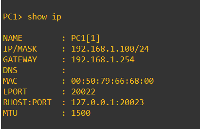
Can the PC ping both 192.168.1.1 and 192.168.1.2?
Can 192.168.1.1 ping 192.168.1.2 and visa versa?
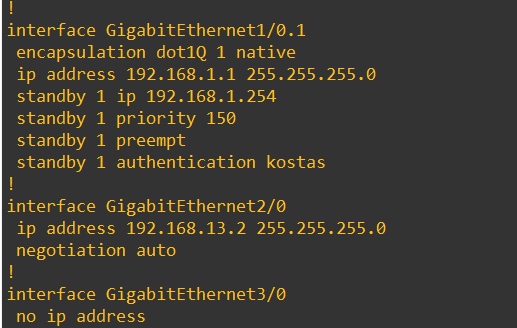
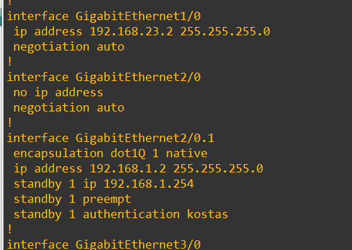
Check the HSRP configuration status using the show standby and show standby brief commands and make sure that the expected and correct statuses are seen.
Just a comment here, there is no need to use subinterfaces here, but yo can get it to work like this, and it would be totally fine. Just make sure that your switch is configured correctly with trunk ports connecting to your routers.
For further troubleshooting with HSRP, take a look at the HSRP troubleshooting lesson. Once you ensure that the above is all correct, and you still can’t ping that particular address, then the problem is a routing problem.
This is exactly the way it should be . Think about this:
R2 does not have any route to the 192.168.23.0/24 network. So, if it is the active router, if you ping 192.168.23.3, the ping will fail.
Similarly, R3 does not have any route to the 192.168.13.0/24 network, so if R3 is the active router, if you ping 192.168.13.3, the ping will fail.
You must configure routing on R2 and R3 so that they learn these networks.
I believe you mean R2 and R3? Yes, if R2 is the active router, then it will be able to ping the 192.168.13.3 address since it is on a directly connected address, and R2 knows about that network. But not the 23.3 address. For this reason, if you want to be able to ping that you should add a route to the routing table of R2. Similarly for R3 when pinging 13.3.
If you shut down the Gi2/0 interface on R2, R2 will still be the active router. In order for SW2 to route traffic to 192.168.23.0/24 you need to have an alternate route to that network via R3. But again, that’s a routing issue that you must configure on the routers.
Again, you must configure routing on all routers to get to know all networks. You can do this either using static routing, or preferably, using a dynamic routing protocol such as OSPF.
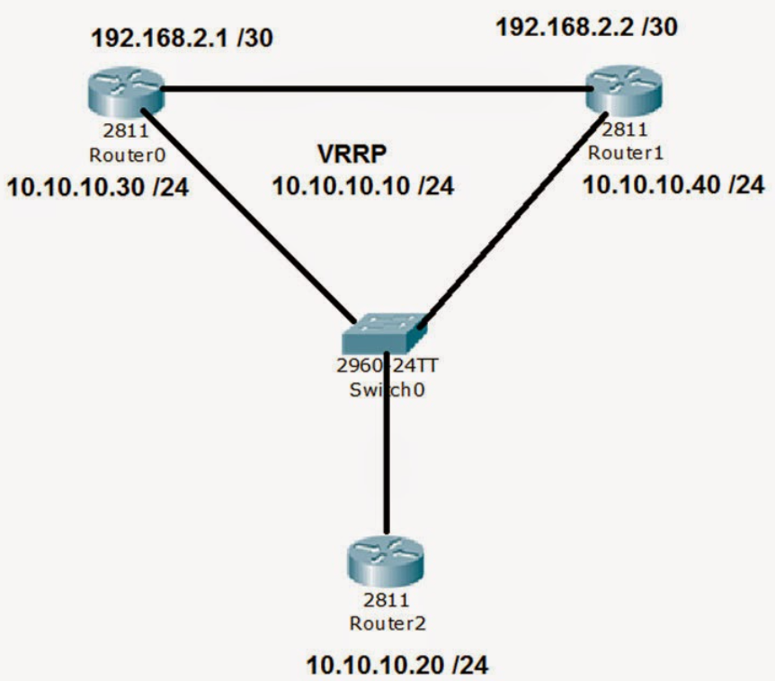
In your example, two switches are being used to create a virtual IP address.
Can I apply HSRP to the switch in the following scenario? One switch is connecting to multiple firewalls via different ports for failover purpose.
Scenario 1:
Switch 1 port 1 is connecting to Firewall A (active)
Switch 1 port 2 is connecting to Firewall B (standby)
Firewall A and Firewall B has same configuration (VRRP) with aggregated virtual address.
Below diagram is similar to my scenario so I used it as an example.
When Firewall A lost the network, the switch will redirect the traffic to Firewall B.
How does switch 1 know which firewall to redirect if there is only one virtual address?
Should I use etherchannel in the above scenario instead? If etherchannel is applied, won’t the traffic lose the packets as the switch is sending packets to both active and standby firewall by its algorithm (round-robin etc.)?
I’m confused about VRRP and HSRP and hoping you could explain the differences and how it could be used. I would like to know what needs to be configure on the switch side.
You have described several different and separate mechanisms that are used to deliver redundancy. First, you mentioned Active/Standby firewalls, which are a setup that has its own redundancy mechanism. If you use this, then you don’t need to use HSRP or VRRP since Active/Standby has its own redundancy operation. You can find out more about this feature at the following lesson:
The above Active/Standby feature is similar to first hop redundancy protocols (FHRP) in that the active device adopts the (virtual) IP address that is used as the default gateway. If that device fails, the standby device becomes active and adopts the IP address. That’s how all FHRPs operate. This means that you don’t need to configure anything else at the switch that connects the two routing devices! That’s the magic of these redundancy protocols.
How does that work? Well, let’s use your diagram for reference. The links to Router0 and router 1 are connected to Layer 2 interfaces on the switch. As soon as one router takes over from the other, it adopts the virtual IP address. The newly active device will send out a gratuitous ARP which is essentially a message letting all devices on the network know that the virtual IP address now corresponds to its own MAC address. Thus, all the hosts on the network will now be sending their traffic to the new MAC address, so the switch knows on which port to send such frames.
EtherChannel should only be used when you want to share traffic across multiple links. In your scenario here, this is not the case, so it would not be beneficial.
Thank you for your detailed explanation as always.
I can find a lot of information about how to configure on the routers as Active/Standby mode.
However, I don’t see much explanation on the switch configuration so I’m trying to figure it out.
From my picture as an example, if I want to configure a layer 2 switch to transmit packets to these Active/Standby firewalls, all I need to is to connect it to port 1 and port 2?
Since the virtual address is 10.10.10.10/24, that means switch 0 does not need to know about IP address of Router 0 and Router 1.
Could you let me know if my understanding is correct for the configuration on the switch.
Let say assign an IP address of 10.10.10.40/24 to Vlan 10.
interface vlan 10
 ip address 10.10.10.40 255.255.255.0
 no shut
Then configure both port 0 and port 1 as trunk ports and assign Vlan 10 to them.
interface range GigabitEthernet 0/1 - 2
 description  Trunk to Firewall
 switchport access vlan 10
 switchport mode trunk
 no shut
The virtual IP address of 10.10.10.10 will be the default gateway.
ip default-gateway 10.10.10.10 255.255.255.250
When the above configuration is done, the switch will send all the packets via port 0 to the Active firewall (Router 0 for example) with its correspond MAC address. Port 1 will not be sending any traffic until Router 0 is down and Router 1 becomes active.
Yes that is correct. The switch doesn’t need to know the IP addresses of router 0 and router 1. Actually, layer 2 switches in general don’t care about the IP addresses found within the header of the IP packet. That’s why they’re Layer 2 switches.
As for the rest of your explanation, yes you can assign an IP address to your SVI of VLAN 10, but keep in mind, you don’t need that SVI at all (unless you simply want to use it to connect to the CLI of the switch, but that’s a different story.)
If the two routers/firewalls are there to provide gateway redundancy to hosts, you don’t need the configuration of the VLAN 10 SVI. You simply connect your hosts to a port on the switch on VLAN 10 and use 10.10.10.10 as the default gateway. Using the mechanisms of ARP and the MAC address table as I described in my previous post, the packets will always go to the active device.
Thank you for the good data. One thing I’m curious about is that I heard that I have to configure vlan when I configure hsrp, can you tell me why? I don’t understand well