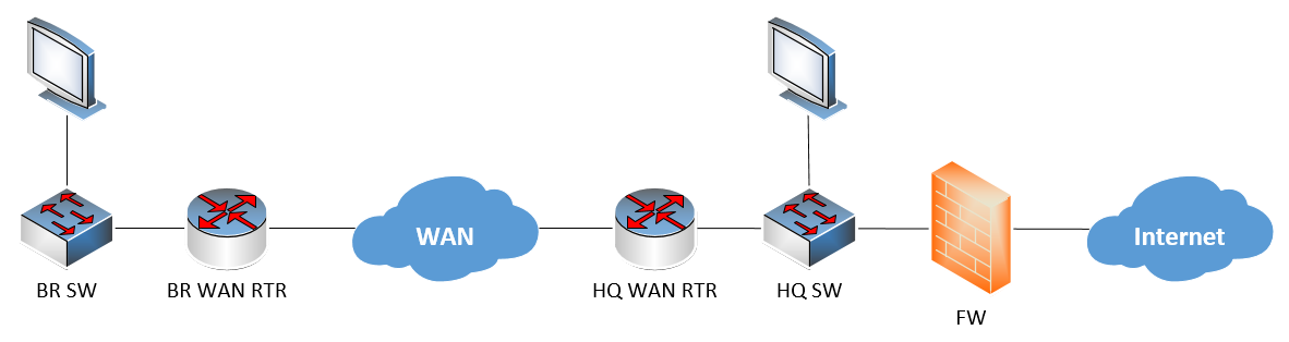
Since the branch network does not have a direct connection to the Internet, but must be routed via the WAN to HQ and then to the Internet, all of the network behind the firewall, including the HQ, WAN, and BR networks are internal. They don’t need to use BGP. For this reason, internal network primarily use IGPs like EIGRP or OSPF.
Now you may say that the WAN connection occurs over the Internet and may require BGP. It may be over the Internet, but it really doesn’t matter how the WAN connection is made. Regardless of whether the WAN is over a private ISP network, or via a tunnelled VPN solution, from the point of view of the internal network, the WAN technology makes both HQ and BR appear to be internal, so no BGP is necessary.
If I have misunderstood your topology, please clarify and I will do my best to respond.
I have one more requirement with the same topology. I need to build a VPN in my firewall ( internet facing FW ) to access all the inside resource which is on the WAN. How could I achieve it?
I assume you mean a site to site VPN. If this is the case, you can take a look at this lesson which describes how to do this using two ASA firewalls, one at each site:
If you want to configure a VPN between an ASA and an IOS router, you can take a look at this Cisco documentation:
For client VPNs where the VPN terminates on the user’s device, take a look at these lessons:
As you attempt to apply these, let us know of any particular questions or troubleshooting that we can help you with!
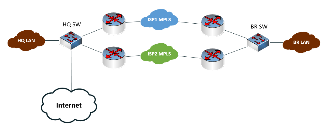
MPLS Network
LAN → SW → RTR1 (ISP1) —> ISP1 MPLS and from the same SW we have → RTR2 (ISP2) connected to the ISP2 MPLS
Internet Network
LAN → Same SW → FW → Internet Cloud
This is the HQ setup. The branches do have the same setup except internet network, branch will have to reach HQ in order to access internet via firewall.
For MPLS
I can able to achieve the failover on the LAN side and will I be able to achieve the failover on the WAN with 2 different ISP’s terminating on the same switch.
For Internet access
I think I have to build a GRE tunnel between BR router and HQ router and point the default route to HQ GRE tunnel internet IP in order to access the internet from the branch, is that correct? please correct me if i am wrong or suggest me a solution for both WAN side failover and internet reachability from branch to HQ
Traffic between HQ and BR uses two redundant MPLS networks, while all traffic from BR to the Internet must traverse the MPLS networks and exit from the HQ internet connection.
Now redundancy can be achieved in multiple ways, and it depends on what you want to achieve. You can have either load balancing between the two MPLS networks, or you can have one MPLS link as the primary one, and the other as the secondary. There are advantages and disadvantages to both.
Load balancing - The advantage is that you have more bandwidth to work with between your sites while maintaining redundancy. This may however not work well if your load balancing algorithms are not correctly configured. You may have services such as VoIP where the voice packets may take one path while the signalling may take another, causing a loss of synchronization. The same may occur with FTP or other similar services. There may also be asyncrhonous routing which means one path is used for sending, while the other for receiving which may not be suitable for some services. In such cases, load balancing algorithms should be employed appropriately to avoid such situations.
Active/passive failover - This solution is mush simpler to implement, and you avoid the situation of syncrhonization altogether. However, you do lose out on the use of the bandwidth of the backup MPLS connection.
The solutions for the connection between HQ and the BR are actually not directly related to MPLS. They can be seen independently from the MPLS network, as that network can be approached like a “black box” meaning, it connects the two routers on either end of the link, but the mechanisms of MPLS are not involved.
For connectivity from BR to the Internet, the same thing applies. It is simply a matter of routing, and no additional VPNs or MPLS configurations are needed. You can approach the problem as if MPLS didn’t exist, and the connection between the routers at HQ and BR are directly connected.
Hello, I just have couple of questions, which relate actually to both HSRP and VRRP. First, more of a statements to confirm my understanding:
With both HSRP and VRRP configuration ends up with a pair of routers/L3Switches having three IP addresses and three MAC addresses where 1 interface (active) has two of them - ‘native’ and virtual and both of them valid. So traffic can be directed to either of the three and all three would work.
For outbound traffic from the paired routers what is the source IP/MAC they would have - virtual or ‘native’? If native how that would work for return traffic if active switch goes down?
Should there be a direct connections between routers/switches 1 and 2 for HSRP or VRRP to work (in addition to downstream connections)?
If in pair the router 2 (the active) has upstream (not HSRP and not tracked) interface going down then traffic stops? Would having direct interconnect between routers 1 and 2 help in this case? (So traffic would go through upstream interface on router 1, then interconnect, then downstream interface on router 2).
Would it make sense to configure HSRP/VRRP also on the upstream interfaces? Would not that improve redundancy, so from either side we have single IP to direct traffic to (on core routers, for example, the ‘clients’ could be on either side)? Though seems we would need then tracking enabled in both directions or maybe have indeed L2 ‘interconnect’ between pair members to send traffic in ‘z’ pattern through both routers from source to destination when one interface fails.
Also, on a side note - looking on diagrams it sometimes perplexing see workstation connected to two routers. Technically, that would not work. Under most ‘normal’ circumstances. So the brain (at least mine for sure) needs to make an additional click to imagine a L2 switch between workstation(s) and the routers. Putting a switch on the diagram is not much of an effort but sure relieves often overloaded student brain from making this additional effort. Just a suggestion.
Yes that is correct. You could use any of the IP addresses and traffic would be forwarded. But you would only achieve redundancy if the virtual IP address is used by hosts, otherwise, in the event of a failure, you could lose connectivity.
Question 2:
In most cases, it would be the physical IP address of the active device. You can see this in practice if you do a traceroute outside of the subnet, from a host that uses an HSRP or VRRP pair as the default gateway. You will see the IP address of the physical interface as the source of the response. Whether it is the physical IP or the virtual IP, this is only for traffic that is inbound into the subnet (outbound from the point of view of the router pair) which does not affect the functionality of HSRP/VRRP.
HSRP and VRRP will communicate with each other only via the subnet that they are providing gateway redundancy for. They communicate using the multicast addresses 224.0.0.2 and 224.0.0.102, both of which are in the range of non-routable multicast addresses, so such messages stay within the subnet. Therefore, the HSRP interfaces can only communicate within the subnet they are providing redundancy for.
If an upstream link goes down, and that link is not tracked, then the topology will fail. HSPR does not share routing information, therefore, even if you had a link between the routers, traffic could not be routed to the other device via such a link. This is the reason why tracking interfaces was introduced into HSRP to deal with such situations.
It is possible to configure HSRP on the internet-facing interfaces to provide redundancy for traffic that is coming into the enterprise network. You must keep in mind, however, that the functionality of HSRP in this direction is a completely independent operation of any HSRP configuration on the inside-facing interfaces. For Internet-facing connections, there are other options that may be more suitable than HSRP including BGP dual and multihomed edge network designs, as well as dual firewall implementations. What you choose depends upon the equipment you have, and what you actually want to achieve.
Yes, in such cases, there is actually a switch there. I’ll let Rene know…
I am more concern about internet for branch office. The branch office is connected to the same ISP as the HQ, both the edge routers are using BGP as a routing protocol. I have infected a default route in HQ bgp configuration and the same has been received in branch office router and I could be able to reach the internet. Here the problem is I have same setup for almost 40 sites each site has HQ and branch with independent MPLS links, will I be able to inject default route for each HQ router for branch to reach internet or is there any way we can accomplish in different like GRE tunneling?
If I have understood correctly, you have a connection to the Internet only at the HQ, and you want all 40 branches, which are interconnected via MPLS, to reach the Internet via HQ, correct?
If that is the case, then you can indeed do this by simply injecting the default route using BGP to all branch routers, leading them to send all default traffic to the HQ, and then on to the Internet. You can find out more about how to do this at the following lesson about MPLS:
Alternatives that may be useful for you in such a situation is to use DMVPN which uses a hub and spoke topology of multipoint GRE tunnels. This would replace your MPLS network, so I don’t know if that’s something that you’d be willing to do.
The advantages are that the configuration is very simple, regardless of the number of spokes you have, so it is a scalable solution, and routing in such a network is also straightforward. You can find out more about DMVPN at the following lesson, as well as several subsequent lessons on the topic:
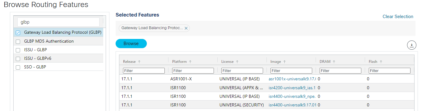
One way to verify if a feature is available on a particular platform/IOS combination is to use Cisco’s Feature Navigator. Using this tool, I see that the latest version of the ISR 4331 (17.2.1r) does not support GLBP. However, previous IOS versions not his platform, such as 3.16S IOS XE do support GLBP. (You will have to go into the “Archived Data” section to see the older IOS versions.)
The only platforms with the latest software that support GLBP are those shown below:
I am creating a HSRP / static routing lab, and unable to make it work.
Where does a L2 device forward a packet when destined to a Vlan?
IOU7#ping 192.168.1.2
Type escape sequence to abort.
Sending 5, 100-byte ICMP Echos to 192.168.1.2, timeout is 2 seconds:
.....
Success rate is 0 percent (0/5)
IOU7#ping 192.168.1.1
Type escape sequence to abort.
Sending 5, 100-byte ICMP Echos to 192.168.1.1, timeout is 2 seconds:
!!!!!
Success rate is 100 percent (5/5), round-trip min/avg/max = 1/1/1 ms
IOU7#ping 192.168.1.100
Type escape sequence to abort.
Sending 5, 100-byte ICMP Echos to 192.168.1.100, timeout is 2 seconds:
.....
Success rate is 0 percent (0/5)


IOU8:
IOU8#show running-config | i ip route
ip route 1.1.1.0 255.255.255.0 192.168.78.7
IOU8#show ip int brief | ex unass
Interface              IP-Address      OK? Method Status                Protocol
Ethernet0/1            192.168.78.8    YES manual up                    up
Vlan1                  192.168.1.1     YES manual up                    up
IOU9:
IOU9#show runn | i ip route
ip route 1.1.1.0 255.255.255.0 192.168.79.7
IOU9#show ip int brief | ex unass
Interface              IP-Address      OK? Method Status                Protocol
Ethernet0/1            192.168.79.9    YES manual up                    up
Vlan1                  192.168.1.2     YES manual up

IOU7:
IOU7#show ip int brief | ex unass
Interface              IP-Address      OK? Method Status                Protocol
Ethernet0/0            192.168.78.7    YES manual up                    up
Ethernet0/1            192.168.79.7    YES manual up                    up
Loopback0              1.1.1.1         YES manual up                    up

IOU7#show runn | i ip route
ip route 192.168.1.0 255.255.255.0 192.168.78.8
ip route 192.168.1.0 255.255.255.0 192.168.79.9
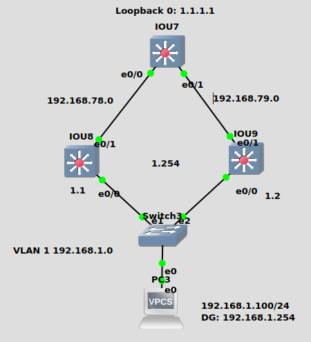
In the topology you have, if you have correctly configured HSRP between the IOU 8 and IOU9, then any packet sent from the PC to the default gateway and beyond will be forwarded by the L2 switch to the virtual MAC that corresponds with the currently active L3 switch. You can see the virtual MAC in the output of the show standby command. More on that can be found at the following lesson:
Now concerning your pings that have failed, notice that your ping to 192.168.1.1 is successful but not to 192.168.1.1. Also note that in the output of the show ip int brief | ex unass command on IOU9, the VLAN1 interface shows Status up, but nothing under the Protocol column. (Not sure if it is a typo, but I’m assuming it isn’t). This indicates to me that the VLAN1 interface on IOU9 is not active, and for this reason is not responding. Check your HSRP configuration, as well as your VLAN configuration on both L3 switches. Also, try some incremental pings, checking to see if the PC pings the virtual IP as well as the two physical IPs of the IOU8 and IOU9 devices.
Check those points out to continue your troubleshooting and let us know how you get on…
Sorry for the Typo, in fact i can reach all Vlan 1 IPs, 1.1, 1.2 and 1.254 from PC and I believe HSRP is configured correctly.
IOU9#show runn int vlan 1
interface Vlan1
 ip address 192.168.1.2 255.255.255.0
 standby 1 ip 192.168.1.254
end
IOU9#show standby brief
                     P indicates configured to preempt.
                     |
Interface   Grp  Pri P State   Active          Standby         Virtual IP
Vl1         1    100   Active  local           192.168.1.1     192.168.1.254
IOU9#show standby
Vlan1 - Group 1
  State is Active
    2 state changes, last state change 2d17h
  Virtual IP address is 192.168.1.254
  Active virtual MAC address is 0000.0c07.ac01 (MAC In Use)
    Local virtual MAC address is 0000.0c07.ac01 (v1 default)
  Hello time 3 sec, hold time 10 sec
    Next hello sent in 1.072 secs
  Preemption disabled
  Active router is local
  Standby router is 192.168.1.1, priority 100 (expires in 10.160 sec)
  Priority 100 (default 100)
  Group name is "hsrp-Vl1-1" (default)

IOU8#show running-config int vlan 1
interface Vlan1
 ip address 192.168.1.1 255.255.255.0
 standby 1 ip 192.168.1.254
end
IOU8#show standby brief
                     P indicates configured to preempt.
                     |
Interface   Grp  Pri P State   Active          Standby         Virtual IP
Vl1         1    100   Standby 192.168.1.2     local           192.168.1.254
IOU8#show standby
Vlan1 - Group 1
  State is Standby
    7 state changes, last state change 00:11:17
  Virtual IP address is 192.168.1.254
  Active virtual MAC address is 0000.0c07.ac01 (MAC Not In Use)
    Local virtual MAC address is 0000.0c07.ac01 (v1 default)
  Hello time 3 sec, hold time 10 sec
    Next hello sent in 0.496 secs
  Preemption disabled
  Active router is 192.168.1.2, priority 100 (expires in 10.672 sec)
  Standby router is local
  Priority 100 (default 100)
  Group name is "hsrp-Vl1-1" (default)

PC3> show ip
    NAME        : PC3[1]
    IP/MASK     : 192.168.1.100/24
    GATEWAY     : 192.168.1.254
    DNS         :
    MAC         : 00:50:79:66:68:02
    LPORT       : 10034
    RHOST:PORT  : 127.0.0.1:10035
    MTU:        : 1500

PC3> ping 192.168.1.1
84 bytes from 192.168.1.1 icmp_seq=1 ttl=255 time=0.521 ms
84 bytes from 192.168.1.1 icmp_seq=2 ttl=255 time=0.918 ms

PC3> ping 192.168.1.2
84 bytes from 192.168.1.2 icmp_seq=1 ttl=255 time=0.791 ms
84 bytes from 192.168.1.2 icmp_seq=2 ttl=255 time=0.913 ms
84 bytes from 192.168.1.2 icmp_seq=3 ttl=255 time=0.874 ms

PC3> ping 1.1.1.1
1.1.1.1 icmp_seq=1 timeout
1.1.1.1 icmp_seq=2 timeout
1.1.1.1 icmp_seq=3 timeout

PC3> ping 192.168.1.254
84 bytes from 192.168.1.254 icmp_seq=1 ttl=255 time=0.727 ms
84 bytes from 192.168.1.254 icmp_seq=2 ttl=255 time=0.922 ms
It’s understood that the PC can reach all of the IP addresses on VLAN 1 including the virtual IP address. This seems to indicate the HSRP is configured correctly. Remember, HSRP offers gateway redundancy to VLAN 1 in your configuration. From the IOU7 point of view, reaching the IPs of the subnet of VLAN 1 requires some routing configuration which also seems to be correct based on your original output. Somewhere along the way, the ping is being dropped. One important question to answer is, is it the echo request or the echo reply that fails? If the packet from IOU7 reaches the PC, then routing in that direction is OK. If it fails on the return, then you may need to troubleshoot the routing in the two HSRP switches. Once you determine which direction the problem is in, it will be easier to further troubleshoot the problem.
As I said, configs look fine at first glance, performing practical troubleshooting with these thoughts in mind would be the next step.
I have a new requirement from my client that I have to implement the HA between two different ISP’s. I have a cisco 2960x LAN base image ( probably stacked with or standalone switch ). As far as I know if switch is a standalone I can run HSRP between two routers on router LAN interface to decide the traffic path, does the same applies when I run the switches in stacked mode also? The next challenge is I don’t have control on my ISP routers, they said since the other ISP link is not the same as their they said it’s not their scope of work. How can I accomplish HA between two links if they can’t help to configure the HSRP on their LAN interfaces? Is there any way I can achieve this with my 2960X switch?
Looking for your valuable suggestion at the earliest.
Getting load balancing between two different ISPs can be challenging sometimes. There are various ways to accomplish load balancing across multiple ISPs and it all depends upon where the load balancing mechanism will be applied.
ISPs typically don’t allow you to mess with their equipment, nor do they actively participate in any features such as HSRP that would require them to pair their devices with those of other ISPs, so this is to be expected.
Load balancing solutions include the use of First Hop Redundancy Protocols (FHRP) such as HSRP, VRRP, or GLBP. But this requires two layer 3 devices within your own network, so it’s not an option for you.
Secondly, you could use BGP in dual-homed designs such as those found within this lesson:
But again, this requires one or more BGP (layer 3) devices that you have control over, and it also requires the ISPs to create a BGP peering with your equipment, something that cannot be done with your 2960.
Thirdly, you could introduce equal cost load balancing, or in the case of EIGRP, unequal cost load balancing where your routing protocol can balance between the two ISPs. You can find out more about it here:
However, once again, with your switch, this is not possible.
For your particular scenario, the only thing I can recommend is to separate your internal network into two subnets, create VLANs within the switch, and direct half of the hosts to one ISP as default gateway and the other half to the other ISP as default gateway. This will load balance, but it will not provide you with HA, because if one ISP fails, half the hosts will lose connectivity.
The only way to achieve HA in this scenario is if you acquire two internal layer 3 devices that will replace the 2960 and perform one of the above-suggested solutions.
Even if the 2960 could connect to both ISPs and somehow load balance, it would still not be an HA solution since the 2960 is a single device, which constitutes a single point of failure.
The explanation is fair enough.
I have one more question, let’s say I have two 2960x are configured as stack and two routers connected as uplinks running hsrp. is this topology works? or should I need to remove the stacking on the switches and connect one switch to one router and connect a cable between two switches and configure as trunk.
I have a setup where there are more than 2 switches in a network with stacked as well but with two routers.
If you have two 2960 switches stacked together, and assuming you still have the same LAN base IOS, then this will not affect the results of the post I previously posted. You can consider the stacked switches as a single device that is still unable to provide FHRP, or redundant BGP or IGP routing.
The HSRP that you would run in such a scenario must be enabled on the ISP routers and not on the 2960, an option that has already been dismissed.
This is a topology that will indeed work, but won’t provide you with the level of HA you need.
The only advantage that a stacked set of switches would provide is high availability at Layer 2. If you had a stack of two 2960s, and you connected each ISP to one of the two switches, then if one switch fails (say its power supply fails), then you will still have connectivity to the second ISP, but only for the devices connected to the good switch. Strictly speaking, this is not HA, but does provide a certain level of redundancy.