Hello Networklessons,
i have a question: i build my topology like yours but when i type in the command sh standby on both switches (SW1 & SW2), both are showing Active Router is local. Why?
Thanks in advance.
Hello Networklessons,
i have a question: i build my topology like yours but when i type in the command sh standby on both switches (SW1 & SW2), both are showing Active Router is local. Why?
Thanks in advance.
Hello Roberto
If both switches see themselves as active router, then this means that HSRP has failed to communicate between the two devices. If one switch doesn’t detect the other switch in its HSRP group, then it assumes it has failed, and it considers itself the active device.
Check to make sure that there is communication between the two devices. Try pinging the real IP address of the SVI of the other switch. Also, ensure that the HSRP configuration (group numbers, virtual IP addresses etc) are correct.
I hope this has been helpful!
Laz
Thank you very much ![]()
Hi Lazaros are all the FHRP be in the new ccna? and why do we have to worry about enabling interface tracking isnt it suppose to be automatic with HRSP if a routers line goes down and it cant forward then wouldn’t the other router take over without a need for decrementation?
Hello Daniel
In the Cisco blueprint, the only item that references any FHRP is 3.5 Describe the purpose of first hop redundancy protocol. Now this most likely doesn’t have much on configuration, but it’s a good idea to understand HSRP, GRRP, and VRRP and know their differences.
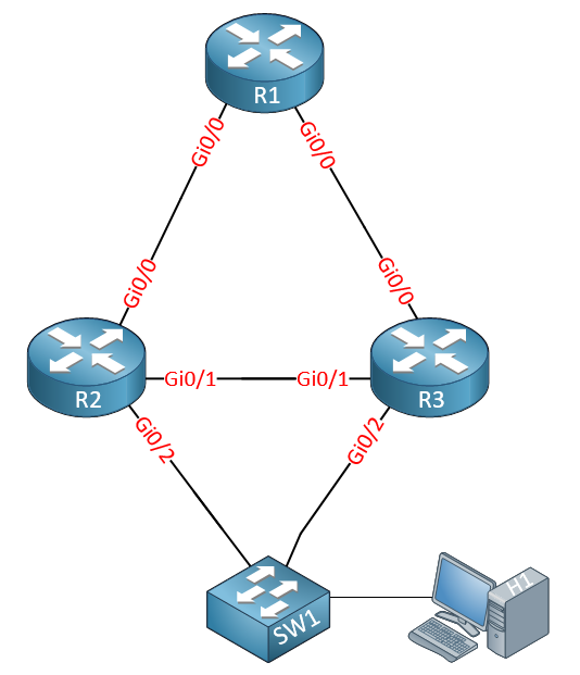
Now as for tracking, of course, if one of the interfaces acting as active or standby goes down, then the devices will be fully aware of this and will react accordingly. However, tracking is important whenever there is a problem with other interfaces on the device, those that don’t participate in HSRP. Take a look at this diagram:
If Gi0/1 on SW2 goes down, HSRP will kick in and all traffic will be directed to SW1. But if Gi0/2 goes down, there is no mechanism inherent to HSRP that will change the active gateway. That’s why tracking must be enabled. Imagine that SW2 has other interfaces that connect to other parts of the network, such as Gi0/5 and Gi0/6 for example. If Gi0/6 goes down, this should not in any way affect the HSRP configurations of Gi0/1 on both switches. But if GI0/2 goes down, then HSRP should kick in. How do we tell the switch which interfaces are important for the specific HSRP group? Using tracking.
I hope this has been helpful!
Laz
Great answer as usual thanks Lazaros
Hi,
I understand HSRP and how to configure it using vlan SVI’s and its all straight forward but I’m just wondering how the adjoining switches and topology would be configured if I were to use routed (L3) ports on the switch or even routers themselves instead of the switches ?
But lets say I am using a similar topology to the one in Renes lab but instead of SVI’s I enter “no switchport” on the interfaces to make them layer 3 ports and then I assign them ip addresses. Each ip address on each interface will have to be on the same subnet in order to put them in the same hsrp group.
The part where I’m stuck is how would these normally tie in with the rest of a topology on the side of the network where the Pc is sitting ?
ie. like would there have to be two other switches there with L3 ports ? and then the link addresses advertised into a dynamic routing protocol or would a simple hub just connecting the two switches to pc work or how is this type of topology normally setup when using routed ports instead of SVI’s?
I’m having trouble understanding how this would be configured in a topology as each L3 “link” has to be in its own subnet but also at the same time needs to be in the same subnet in order to be in the same hsrp group ?
Hello Sean
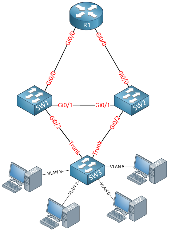
The primary difference between the scenarios that you are describing is the fact that with a router (or a routed port on a switch), you can only serve one single subnet with a redundant gateway using HSRP. Using Layer 3 switches and SVIs, you can serve multiple subnets with redundant gateways using the same two physical links. Take a look at the following diagram:
Now take a look at this:
In both cases, the physical topology is the same, but you can see that the second case will provide you with redundancy for multiple (dozens or even hundreds!) subnets.
I hope this has been helpful!
Laz
Excellent explanation.
Thanks Lazaros.
Hi Lazaros,
For the configuration examples in the HSRP page under SW1 there is no ip sla set? Shouldn’t we set the ip sla for interfaces on each MLS? Also, if you are ok with just tracking the connected interface closest to switch to router and not far end of router can you just use the command:
standby 1 track gi0/2 without the “line-protocol” part? What does the extra 1 after track signify in the lesson because on packet tracer the command standby 1 track 1 the “1” isnt allowed?
Would the commands be different for ip sla if instead of 1 mutual vlan we were working intervlans or a physical interface what should the command output look like for those instead of the below:
SW2(config)#track 1 ip sla 1
SW2(config)#interface Vlan 1
SW2(config-if)#standby 1 track 1 decrement 60
In my own network I put standby as:
interface GigabitEthernet0/1.13
 encapsulation dot1Q 13
 ip address 192.168.6.2 255.255.255.0
 standby 13 ip 192.168.6.3
 standby 13 preempt
 standby 13 track GigabitEthernet0/0
Sorry for so many question I went down a rabbit hole with this one
Hello Daniel
Not necessarily. In this particular case, SW2 has a priority of 150, so it is the active router. The IP SLA configuration will make the priority drop by 60 in the event the IP SLA goes down. This will result in SW1 having the higher priority, and thus will become active. Once the SLA is restored, the priority of SW2 will go back up and it will become the active gateway. So this can be done with an IP SLA config on only one switch.
The command requires the tracked object number to be specified asfter the keyword track. Take a look at the following:
SW1(config-if)#standby 1 track ?
  <1-1000>  Tracked object number

SW1(config-if)#standby 1 track
That 1 signifies the SLA that you have created. Packet tracer doesn’t support all of the commands available on real IOS devices, so you may run into some such situations.
Tracking should use the same syntax regardless of whether you are using an SVI or a physical interface. The track feature always requires a tracked object number after the keyword track, at least on the IOS and platforms I am using. It may be the case that some other platforms use slightly different syntax, like the one you state in your post, where you indicate the interface directly.
I hope this has been helpful!
Laz
I am still a little confused why am I able to put the command track gi0/0 above and have it go through packet tracer if it wont work. In order to track that interface I should have wrote the commands: “track 1 interface gi0/0 line-protocol” and then “inter vlan 13 standby 13 track 1”? And why is this the case sorry I am very confused here
Hello Daniel
Indeed in packet tracer for both routers and layer 3 switches, the command standby 13 track gigabitethernet0/0 will work. I checked it too and it does function. However, on CML using the IOSv, this option is not available and requires the syntax described in my post above.
Both will work, but it depends upon the syntax required by the specific platform.
I hope this has been helpful!
Laz
Hi Rene
I have a question with the objects that can be created in a track like this:
Switch (config) # track 1 list threshold weight
Switch (config-track) # object 1 weight 15
Switch (config-track) # object 2 weight 20
Switch (config-track) # object 3 weight 30
Switch (config-track) # threshold weight up 30 down 10
How do you associate these objects to certain interfaces or certain IP sla?
Hello Jorge
Object tracking allows you to create specific objects to track, and based on their state, respond in some way. Object tracking separates the creation and definition of an object from the actual tracking of the object.
In the above configuration, you have created a track list. This track list tracks multiple objects at the same time. In any case, once an object or a track list is defined, it can then be referenced when tracking.
For example, once your tracked list is created, you would then go to the interface for which you would like to use this tracked object, and configure something like this:
Switch(config)# interface gigabitethernet 0/1
Switch(config-if)# standby 15 track 1 decrement 10
In this case, the “1” in the command references the track list that you created. This is the object to be tracked.
If you wanted to reference it using an IP SLA, you would once again reference the object using its object number, in this case, “1”.
More info about these commands can be found here:
I hope this has been helpful!
Laz
Hi,
Can someone confirm please if HSRP requires the use of the same router models? Also is it possible to use the track function on one router too track an ethernet connection and on the standby router a serial connection?
Thanks again.
Hello Lee
HSRP, like all first-hop redundancy protocols, is platform-independent. You can even run it between an ASR router and an L3 switch if you like. Additionally, you can track whatever interface you like on one device, while tracking another on another device. There is no restriction on the type of tracking you apply to each device.
I hope this has been helpful!
Laz
Hi Laz,
Do you know by any chance why would the hsrp configured on a vlan from time to time change its own configurations ?
so we have 2 5k nexus switches with vpc configured and hsrp for some reason between them, and I have noticed that from time to time in the vlan where we have all these hsrp configurations it appears that “mtu 9216” and “no shutdown” command would appear and disappear. state change does not change, everything seems to be working fine.
Also, Another question.
What is the point of using hsrp with nexus VPC, isnt it a whole point of using vpc for redundancy ?
I have tried finding a purpose of that , but the only thing I could find is an explanation of how it all works. here is a good article about it https://networkdirection.net/articles/virtual-port-channels-vpc/vpcwithhsrpvrrp/
but what is the purpose of using hsrp with vpc ?
myabe the reason is just to have a gateway ?
thank you
Regards,
Max
Hello Maksym
So from my understanding, your topology, as well as your HSRP configuration, are working fine. There are no state changes in your HSRP configuration. When you say that the “mtu 9216” and “no shutdown” commands would appear and disappear, where do you see that? In the configuration of the VLAN interface itself? So when you do a show run interface vlan 100 one time, you see these commands, and the next time you don’t? Please clarify, or give us some output of your show commands to confirm.
For your second question…
HSRP and vPC do two different things.
vPC allows you to interconnect two Nexus switches making them appear as a single logical node to other devices. vPC essentially doubles the available bandwidth (by simply adding a second device through which traffic can pass) while maintaining a layer 2 loop-free topology (no STP needs to function). So vPC primarily scales up the size of the Layer 2 network.
HSRP however, is a gateway redundancy protocol, meaning it operates on L3.
Now having said that, HSRP and vPC do work well together. When configured together, you have the following advantages:
I hope this has been helpful!
Laz
Hello Laz, thank you for the response.
Yeh looks like the HSRP and VPC was just for the gateway purpose.
in regards of the other issue. yes this is pretty much what happens. I have created a script to monitor any changes on the switches, and I have noticed that a few switches in VPC mode would do it for a few vlans, the funny thing there is another vlan that is compeltelly shutdown on these nexus switches and they have the same thing happening on them even thou they are in administratively shutdown state
So I started to look into it.
I have followed with my management and they have advised that there is nothing automated to do such a thing.
Please see below
this is what it looks like at one point
interface Vlan207
  no ip redirects
  ip address x.x.x.x/x
  hsrp version 2
  hsrp 207
    authentication md5 key-chain x
    preempt
    priority 105
    timers  1  3
    ip x.x.x.x
  no shutdown
  mtu 9216
also what it looks like “sh run int vlan 207 all”
interface Vlan207
  no ip redirects
  ip address x.x.x.x/x
  ip port-unreachable
  ipv6 nd hop-limit 64
  ipv6 nd mtu 1500
  ipv6 nd ns-interval 1000
  ipv6 nd ra-interval 600
  ipv6 nd reachable-time 0
  ipv6 nd retrans-timer 0
  ipv6 redirects
  ipv6 mld version 2
  ipv6 mld robustness-variable 2
  ipv6 mld query-interval 125
  ip arp timeout 1500
  ip arp gratuitous update
  ip arp gratuitous request
  no hsrp bfd
  hsrp version 2
  hsrp delay minimum 0 reload 0
  no hsrp use-bia
  hsrp 207
    authentication md5 key-chain x
    name hsrp-Vlan207-207
    mac-address xxxx.xxxx.xxxx
    preempt
    priority 105
    timers  1  3
    ip x.x.x.x
  no shutdown
  mtu 9216
  bandwidth 1000000
  delay 1
  medium broadcast
  snmp trap link-status
  no description
  carrier-delay msec 100
  load-interval counter 1 60
  load-interval counter 2 300
  no load-interval counter 3
  mac-address xxx.xxxx.xxxx
and this is what it looks like the other second
interface Vlan207
  no ip redirects
  ip address x.x.x.x/x
  hsrp version 2
  hsrp 207
    authentication md5 key-chain x
    preempt
    priority 105
    timers  1  3
    ip x.x.x.x
also what it looks like “sh run int vlan 207 all”
interface Vlan207
  no ip redirects
  ip address x.x.x.x/x
  ip port-unreachable
  ipv6 nd hop-limit 64
  ipv6 nd mtu 1500
  ipv6 nd ns-interval 1000
  ipv6 nd ra-interval 600
  ipv6 nd reachable-time 0
  ipv6 nd retrans-timer 0
  ipv6 redirects
  ipv6 mld version 2
  ipv6 mld robustness-variable 2
  ipv6 mld query-interval 125
  ip arp timeout 1500
  ip arp gratuitous update
  ip arp gratuitous request
  no hsrp bfd
  hsrp version 2
  hsrp delay minimum 0 reload 0
  no hsrp use-bia
  hsrp 207
   authentication md5 key-chain x
    name hsrp-Vlan207-207
    mac-address xxxx.xxxx.xxxx
    preempt
    priority 105
    timers  1  3
    ip x.x.x.x
thank you Laz.