HSRP (Hot Standby Routing Protocol)

Hello Maksym

Hmm, that is indeed strange. I haven’t come across something like this before. There are two things to address here: the statements found within the config, and the actual operation of the device.

For the no shutdown command, when an interface is up and running, of course, the no shutdown command is valid for such an interface, whether it appears in the configuration or not. So whether it appears or not doesn’t actually affect its operation. Some IOS and NX-OS versions display it in the config while others do not. I haven’t come across a situation where it is intermittently displayed, however.

Secondly, for the MTU value of 9216 appearing and disappearing, I’d like to ask, do you find that the actual value of the MTU fluctuates as well? For example, if you were to try to send a series of pings that traverse this VLAN with an MTU set to 9216, do you find that sometimes they pass through and others they don’t? In other words, is the actual operation of the switch affected by whether or not the MTU value is displayed? I assume not. In any case, this MTU value can be assigned either on a particular Layer 3 interface, or an SVI directly, using one of the following methods:

  1. for a particular interface using the mtu 9216 command in the interface configuration mode
  2. using system jumbomtu 9216 in the global configuration mode to set the value for all interfaces on the whole switch
  3. by setting the MTU using the policy map for the class-default class like so:
switch(config)#policy-map type network-qos jumbo
switch(config-pmap-nq)#class type network-qos class-default
switch(config-pmap-c-nq)#mtu 9216
switch(config-pmap-c-nq)#exit
switch(config-pmap-nq)#exit
switch(config)#system qos
switch(config-sys-qos)#service-policy type network-qos jumbo

Depending on the NX-OS version, some options may not be available. In any case, if the MTU is configured in one of these ways, it may be that it appears and disappears depending upon the way in which it was configured. Since your configuration has a vPC as well, you may want to ensure that the configuration synchronization between the switches is taking place correctly too. I don’t have a Nexus device handy to check it out, but you may want to see how the MTU was set, which may shed some light on this strange behavior.

Finally, you stated that:

Is this the case for the no shutdown command as well? That is highly unusual since this command indicates that the interface is indeed up, even though you state that it has been administratively shutdown. It that is the case, then this is a strange situation indeed!

Looking forward to hearing your responses!

I hope this has been helpful!

Laz
I built the lab in the lesson and paste the config you provided. However, I can not ping from the router to 192.168.1.x network. I did not want to alter the lab to make it work.

Hello David

I took a look at the final configs at the end of the lesson and I didn’t find any readily perceivable problem with the configurations.

I suggest you follow the lesson from the beginning, step by step, and if there is indeed an incorrect configuration, you should be able to discover it along the way. That way it will help you understand each step, and help you identify where the problem may possibly be.

Let us know how you get along, and if you get stuck somewhere, feel free to let us know!

I hope this has been helpful!

Laz

Hi Rene,

How are you able to physically connect the host to two different MLS’s using only 1 interface from the host side ?

Br,
Amr

Hello Amr

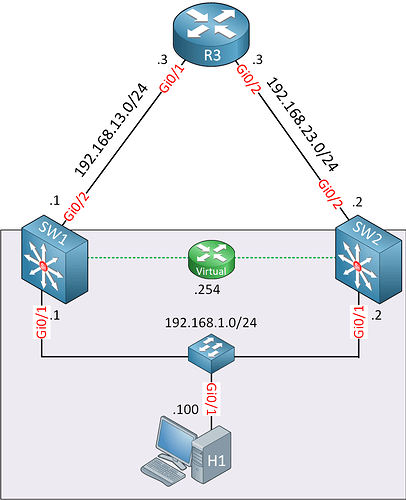
I understand your confusion. It is supposed that there is a Layer 2 switch there. As you can see, the Gi0/1 interface of SW1, the Gi0/1 interface of SW2, and the NIC of H1 are all on the same subnet of 192.168.1.0/24. This means that they are on the same Layer 2 segment. Ideally, there should be an icon of a switch there.

I will ask Rene to update the diagram for clarification.

I hope this has been helpful!

Laz

1 Like

Thanks Laz!
It’s clear now.

Br,
Amr

1 Like

Hi Rene

I have a question. In the multilayer switch config, we have not assigned the ip 192.168.1.1 to Gi0/1 . Similalry for Gi0/2
Only under vlan config , the ip is present (192.168.1.1). Can you pls explain how Gi0/1 which is connected to host gets the ip configured?

Hello Anath

When working with multilayer switches, there are two options that you can use for assigning IP addresses to Layer 3 interfaces.

In the example in the lesson, Rene could have configured Gi0/1 on both switches as a routed interface. A routed interface is a Layer 3 interface to which you can assign an IP address. Essentially, such a configuration makes that interface function the same as an interface on a router.

To configure a routed interface, use the following commands:

SW1(config)#interface gi0/1
SW3(config-if)#no switchport
SW3(config-if)#ip address 192.168.1.1 255.255.255.0

The second option is to create what is known as a Switched Virtual Interface, or an SVI. This is a virtual interface created on the specific VLAN (VLAN1 in the case of the lesson), and this is what Rene created in the lesson. All Layer 3 configurations, such as IP address and subnet mask are configured there. In that way, all hosts connected to an access port on VLAN1 on the switch have direct access to that Layer 3 interface as a default gateway. The advantage here is that multiple hosts can connect to multiple access ports on VLAN 1 and have access to that default gateway.

In the case of the routed port, you would need another physical switch to connect to that port for multiple hosts to access the default gateway.

You can find out more information about SVIs, routed ports, and related issues, take a look at the following lesson:

You may also find the following NetworkLessons notes useful:

I hope this has been helpful!

Laz

Hello network lesson,
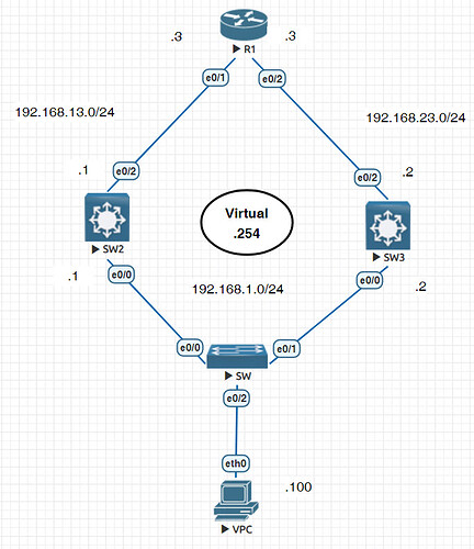
I use eve-ng , R1 , SW2, SW3 run RIP, VPC set gateway as 192.168.1.254, R1 can ping 192.168.1.254 but cannot ping VPC (192.168.1.100). I unknown whether it is the reason from eve-ng emulator.

R1

interface Ethernet0/0
 no ip address
 shutdown
!
interface Ethernet0/1
 ip address 192.168.13.3 255.255.255.0
!
interface Ethernet0/2
 ip address 192.168.23.3 255.255.255.0
!
interface Ethernet0/3
 no ip address
 shutdown
!
router rip
 version 2
 network 192.168.13.0
 network 192.168.23.0

SW3

no ip domain-lookup
ip cef
no ipv6 cef
!
!
!
spanning-tree mode rapid-pvst
spanning-tree extend system-id
!
vlan internal allocation policy ascending
!
track 1 interface Ethernet0/2 line-protocol
!
interface Ethernet0/0
!
interface Ethernet0/1
!
interface Ethernet0/2
 no switchport
 ip address 192.168.23.2 255.255.255.0
 duplex auto
!
interface Ethernet0/3
!
interface Vlan1
 ip address 192.168.1.2 255.255.255.0
 standby 1 ip 192.168.1.254
 standby 1 timers msec 100 msec 300
 standby 1 priority 150
 standby 1 preempt delay minimum 60
 standby 1 authentication md5 key-string MY_SECRET_KEY
 standby 1 track 1 decrement 60
!
router rip
 version 2
 network 192.168.1.0
 network 192.168.23.0
 no auto-summary
!
ip forward-protocol nd

SW2

no ip domain-lookup
ip cef
no ipv6 cef
!
!
!
spanning-tree mode rapid-pvst
spanning-tree extend system-id
!
vlan internal allocation policy ascending
!
interface Ethernet0/0
!
interface Ethernet0/1
!
interface Ethernet0/2
 no switchport
 ip address 192.168.13.1 255.255.255.0
 duplex auto
!
interface Ethernet0/3
!
interface Vlan1
 ip address 192.168.1.1 255.255.255.0
 standby 1 ip 192.168.1.254
 standby 1 timers msec 100 msec 300
 standby 1 preempt delay minimum 60
 standby 1 authentication md5 key-string MY_SECRET_KEY
!         
router rip
 version 2
 network 192.168.1.0
 network 192.168.13.0
 no auto-summary
!
ip forward-protocol nd

Hello Chun

At first glance, I don’t see any problems with your configuration. I suggest you take a look at the routing tables of SW2 and SW3 to ensure that they will forward the packets to the VPC correctly, and that return traffic will be forwarded corectly as well. You can also attempt pings in the other direction, from the VPC to R1, and from the VPC to the e0/2 interfaces of SW2 and SW3. This way you can detect where the communication is breaking down.

Once you determine that, you can then move to resolve the problem. Let us know how you get along and if we can be of further help for you!

I hope this has been helpful!

Laz

Thx replay,
I find if switch use interface not vlan 1 , it will work. It should be problem of eve-ng emulate.
How to move this to resolve the problem

Hello Chun

Hmm, that’s interesting. That would be one solution to the problem. It may be that the EVE-NG emulator is at fault. I’m not sure how you can resolve this issue within the EVE-NG environment. Have you tried emulating the same thing on GNS3 or VIRL? If you have access to those emulators it may be worth testing it out. If you do so, let us know your results.

I hope this has been helpful!

Laz

Hello ,
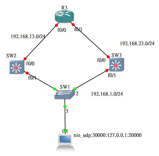
I have tried to use GSN3 0.87 version. R3 can successfully ping PC, but PC with gateway (192.168.1.254) cannot ping R3. R3 cannot ping hsrp virtual ip(192.168.1.254).
I think it should be GNS3 bug.
I upload gns3 project file, you can try.
HSRP.zip (53.7 KB)

Hello Wonglili

It seems that the files you sent contain only the console and aux configs of the routers so I was unable to get it to work in GNS3.

In any case, if you are able to ping successfully from R1 to the PC, that means that routing IN BOTH DIRECTIONS is successful. Remember that ping has a request and a reply, so communications in both directions are OK.

Now this means that when you are pinging from the PC to R3, you are using a different destination IP address of R3 than was used in the ping from R3 to the PC. Otherwise, the ping would be successful.

Configuring HSRP with routing protocols can get tricky. You must also keep in mind that RIP advertisements (like all routing protocol advertisements) are never sent by the virtual IP address, but by the real IP addresses of the redundant HSRP devices. Thus you must ensure that RIP will always use the active HSRP device as the next hop.

Now the fact that you can’t ping the virtual IP address from R3 tells me that there is indeed a routing problem. Take a look at the routing tables of all devices to determine where the issue may lie.

I can’t confirm that the problem is with GNS3, but you can do some more troubleshooting, based on some of the information given here, and let us know how you get along.

I hope this has been helpful!

Laz

Quick question. Is there a Cisco ‘Best Practice’ or something along those lines that describes a recommendation/benefit of establishing an OSPF peer relationship between 2 HSRPv2 Switches via a dedicated routed link or via an SVI between both switches?

Thank you so much

Hello Jacob

It really depends upon what you want to achieve. Remember that HSRP and other gateway redundancy protocols are typically used to deliver gateway redundancy to end hosts. That means that the HSRP-enabled interfaces should be facing a subnet with hosts, and not with routers that can route traffic further downstream…

Now interfaces that are participating in HSRP can be configured to run OSPF, but it is generally not recommended. Virtual IP addresses are not shared using OSPF, but only the real addresses assigned to the interfaces. Now two routers that are running HSRP can run OSPF between them on interfaces other than the ones participating in HSRP. So uplink connections, as well as L3 connections between the switches (that don’t carry the HSRP signalling data between the switches) can run OSPF with each other and with other routers upstream.

To help you out more effectively, can you share with us what it is that you want to achieve?

I hope this has been helpful!

Laz

Hello Laz,

Our goal is to achieve a high-available, highly-redundant network in order to support a 24x7 inpatient hospital. In our initial design, we were just running an HSRP pair on 2 Cisco 9500s switches with 1x100G L2 interconnect trunk between the two, but it was suggested by a colleague that we create a peering via an SVI, so I was curious what the benefits/impacts were as I have not see a ton of documentation referencing that concept.

Hello Jacob

A peering between SVIs simply means that the “standby” commands are placed under a VLAN interface (which is an SVI). In such a case, the communication between those SVIs that establishes the HSRP peerings can take place via the trunk that you have configured between the switches, or via the actual interfaces facing the hosts, as is the case in this lesson.

Alternatively, you can have Layer 3 interfaces which are physical interfaces that have been assigned an IP address, under which the standby commands have been issued. In this case, the peering communication between the interfaces in question will not traverse the trunk between the switches, but will necessarily take place via the switch to which both interfaces are connected. This is a topology that is similar to what we see in the lesson.

Since you have a trunk between your switches, I am assuming that your standby commands are issued under the VLAN interfaces. If you are using layer 3 interfaces, then no peering communication takes place over that trunk.

Let us know more about your topology so we can clarify further.

I hope this has been helpful!

Laz

what if we want redundancy for multiple vlans in our network? @ReneMolenaar

Hello Viki

That can be easily done. Let’s take a look at the diagram in the lesson once again:

Imagine that the Gi0/1 interfaces on SW1 and SW2 are trunks, and they are carrying three VLANs: 10, 20, and 30. Imagine that the switch at the bottom has three ports where Gi0/1 is on VLAN10, Gi0/2 is on VLAN 20 and Gi0/3 is on VLAN 30. In order to create three default gateways for these three VLANs where SW1 and SW2 are operating in a redundant fashion, you simply configure the following:

SW1:

interface Vlan10
 ip address 192.168.10.1 255.255.255.0
 standby version 2
 standby 10 ip 192.168.10.254
!
interface Vlan20
 ip address 192.168.20.1 255.255.255.0
 standby version 2
 standby 20 ip 192.168.20.254
!
interface Vlan30
 ip address 192.168.30.1 255.255.255.0
 standby version 2
 standby 30 ip 192.168.30.254

SW2:

interface Vlan10
 ip address 192.168.10.2 255.255.255.0
 standby version 2
 standby 10 ip 192.168.10.254
!
interface Vlan20
 ip address 192.168.20.2 255.255.255.0
 standby version 2
 standby 20 ip 192.168.20.254
!
interface Vlan30
 ip address 192.168.30.2 255.255.255.0
 standby version 2
 standby 30 ip 192.168.30.254

Just as long as the standby IDs, as well as the subnets used are different, you can create as many HSRP groups as you need for the number of VLANs you have. In this way, the hosts on the bottom switch will have redundant gateways for their respective VLANs.

Now when you have many VLANs set up in this manner, it is a good idea to set the priority higher on SW1 for half of them, and the priority on SW2 higher for the other half. That way the traffic will actually be balanced more evenly across both switches.

I hope this has been helpful!

Laz

1 Like