This topic is to discuss the following lesson:
Dear Sir,
I am really thanks for your lessons it’s help full for me
again thanks
My router is not showing the directly connected routes even after configuring the router.What could be the problem?
Router#sh ip int br
Interface              IP-Address      OK? Method Status                Protocol

FastEthernet0/0        192.168.1.254   YES manual up                    down

FastEthernet0/1        192.168.2.254   YES manual up                    down

Vlan1                  unassigned      YES unset  administratively down down
Router#sh ip route
Codes: C - connected, S - static, I - IGRP, R - RIP, M - mobile, B - BGP
       D - EIGRP, EX - EIGRP external, O - OSPF, IA - OSPF inter area
       N1 - OSPF NSSA external type 1, N2 - OSPF NSSA external type 2
       E1 - OSPF external type 1, E2 - OSPF external type 2, E - EGP
       i - IS-IS, L1 - IS-IS level-1, L2 - IS-IS level-2, ia - IS-IS inter area
       * - candidate default, U - per-user static route, o - ODR
       P - periodic downloaded static route

Gateway of last resort is not set
Most likely it is a cable problem, or there is a speed/duplex mismatch between your router and the other side where it is plugged in.
Hi,
I would like to know the main differences between Branch Routers and Network Edge Routers, please.
You can find that option on the Cisco Router Selector web page:
Thanks! ![]()
Hello David!
An edge router is a router that is found at the “edge” of a corporate or an enterprise network, that is, at the location where you connect to the “outside world” be it the Internet or a private or public WAN. Edge routers are usually designed to handle large amounts of traffic for hundreds or even thousands of users. Additionally, edge routers have many functionalities that would be useful at the edge of a large network such as security, content filtering, dual or multi homed connections (connecting to multiple ISPs for redundancy) and others.
Branch routers on the other hand are smaller, cheaper and are used primarily for remote sites (or a corporate branch office, which is where it gets its name from). They can also be used for a standalone office comprised of a small number of end users. The number of users branch routers can accommodate is usually several dozen and won’t often surpass 100. These routers usually have capabilities such as VPNs to connect to the corporate network and some security features. In general, they are a lower end devices as compared to network edge routers.
There really isn’t a solid line that separates the two types of routers. It all depends on the needs you have at each site. These needs however, more often than not, are derived from the number of end users you have at the site you want to provide for.
I hope this has been helpful!
Laz
Thank you very much! ![]()
A basic question please: I understand the concept of gateway, i.e. if destination IP address is not in my subnet then go via gateway. But what does that packet look like, is the destination IP address that of the router and another/2nd destination IP address that of the intended end destination? Or asked differently if we have Sw1—Router—Sw2, where all hosts on Sw1 are in 192.168.1.0/24 and all on Sw2 are in 192.168.2.0/24, how will the Sw1 know that a packet with dest IP address for 192.168.2.2 needs to go to the router? -or does it learn MAC addresses in this instance from the router, which I assume is the case?
Hello Johan
Using your topology of Sw1—Router—Sw2, where SW1 has a subnet of 192.168.1.0/24 and SW2 has a subnet of 192.168.2.0/24. Let’s say 192.168.1.1 is the default gateway, that is the Router’s IP address.
Now imagine that Host 1 with an IP address of 192.168.1.10 wants to send a packet to 192.168.2.10. It does the following:
- The data is received from the transport layer and encapsulated into an IP packet. The source IP is 192.168.1.10 and the destination IP is 192.168.2.10. These addresses remain the same in the header of the IP packet during the whole trip of the packet from source to destination. They do not change.
- The host determines that the destination is not in the same subnet, so it must send the packet to the default gateway. Now as it encapsulates the IP packet into an Ethernet frame, it uses the MAC address of Host 1 as the source MAC address and the MAC address of the default gateway as the destination MAC address.
- In order to get the destination MAC address, that of the gateway, it must look up the gateway IP address if 192.168.1.1 (which Host 1 knows because it is configured with a default gateway) in its own ARP table. ARP is used to determine an unknown MAC address that corresponds with the known IP address. If it has an entry for the IP address, it uses that MAC address as the destination. If it does not, it sends an ARP request (broadcast) asking for the MAC address on the network segment that corresponds with this IP address.
- Once the MAC address of the default router is determined, the destination MAC address field of the Ethernet frame is populated and the frame is placed on the wire to be sent.
- Once the frame is received by the router, it will deencapsulate it to the network layer, look at the destination IP address and reencapsulate it with the appropriate source and destination MAC addresses, that is, its own and Host 2’s respectively.
So essentially, in the Network layer, the source and destination IP addresses remain the same throughout the path of the packet. In the Data Link layer, the source and destination MAC addresses change for each hop of the path to the destination.
You can find some more information about this topic at the following lesson:
I hope this has been helpful!
Laz
Hey @ReneMolenaar just a minor typo ![]() thanks for the lesson, these refreshers are great
thanks for the lesson, these refreshers are great
In this lesson we will take a look at the difference between switches and routers and I’ll explain you the basics of routing.
In this lesson we will take a look at the difference between switches and routers and I’ll explain to you the basics of routing.
Thanks @witherford.m, just fixed this.
Rene
Hi Rene/Laz,
I emulated similar topology on GNS3, kindly help to clarify the below points. I have the following topology:
R1(Ge0/0) ↔ (Ge0/0)R2(Ge0/1) ↔ (Ge0/1)R3
R1-R2: 192.168.1.0/24
R2-R3: 192.168.2.0/24
So when the routers came up and ip address was configured on interfaces, each interface broadcasts gratuitous arp packet. So my question is when I try to ping from R1 to R3, since the R3 ip is in a different subnet R1 tries to send it to its default-gateway. When gratuitous arp has already informed the mac address why does it it have to send an arp request again to find the mac address of the adjacent port.
Apologies if not clear about my question, attaching snippet from the wireshark capture.
In the image you can see 192.168.2.2(R3-Ge0/1) interface has already announced its mac address, however 192.168.2.1(R2-Ge0/1) again sends an arp request? why does that happen?
Thanks and Regards,
Teja
Hello Teja
When a device is connected and turned on, one of the things it may do is to “announce” its existence to its neighbours within the same network segment using a Gratuitous ARP. Whether this actually happens or not depends on the vendor of the network equipment and the software being run on it. The purpose is useful, as it is an attempt to preemptively populate the ARP caches of neighbouring hosts, eliminating the need to initiate a normal ARP request.
This was especially useful “back in the day” (ARP was defined in 1982!) when bandwidth was scarce and every effort for efficiency was necessary. However, there is no rule or standard that obligates any network device to use the information in a Gratuitous ARP to populate its ARP table. Indeed, some, (actually most) vendors will ignore Gratuitous ARPs in such situations altogether, since sending out another ARP request essentially adds no overhead to today’s high speed networks. And this is indeed best practice, as it mitigates against attacks that involve Gratuitous ARPs with modified MAC addresses.
So in your situation, the router simply ignores the information in the Gratuitous ARP because it has been designed to do so.
I hope this has been helpful!
Laz
Hi there.
I have a question, and I’m not sure where should I post it.
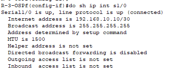
However, I configured an IP address (192.168.10.10 /30) on a serial interface. When I show the interface details it shows me that the broadcast address is (255.255.255.255) as shown in the below figure.
I know that the (255.255.255.255) is the broadcast address, but I was expecting to see the broadcast address to be (192.168.10.11) based on the subnet.
My questions are
![]() Why it shows (255.255.255.255) broadcast address and not the subnet broadcast address,
Why it shows (255.255.255.255) broadcast address and not the subnet broadcast address,
![]() and as I know this address is for all networks, right, but the router does drop broadcast packets destined for other networks, so how is the router going to use this broadcast address (255.255.255.255).
and as I know this address is for all networks, right, but the router does drop broadcast packets destined for other networks, so how is the router going to use this broadcast address (255.255.255.255).
So, I need to understand this, please.
I appreciate your effort.
Hello Ameen
A serial interface is considered a point-to-point network. It is not a multi-access network like Ethernet where you can have more than two hosts on a single network segment. There is only a single destination on the other end of the link.
Now serial links can be assigned IP addresses, but they can also function without IP addresses. These would be called unnumbered IP interfaces. This is because any packets exiting a serial interface will necessarily enter the interface of the device on the other end. The routing table in a router can have an exit interface as the “next hop” without the need for an IP address.
Now having said that, if you want to access a particular router using the serial interface, then you do require an IP address there. Because of the nature of serial links, they will by default automatically use the broadcast address of 255.255.255.255 simply because it has the same result as using the network broadcast address. There is only a single other device on the network so there is no need to be more specific.
However, you can change this if you like by using the ip broadcast-address command under the serial interface configuration.
The configured subnet mask has no effect on what the default broadcast address will be.
I hope this has been helpful!
Laz
Thanks so much, sir.
Hi guys,
Lesson “Introduction to Routers and Routing”. In the explanation about routing vs. switching you explained very well about splitting “MAC domains” - smaller MAC tables (200 MACs instead of 400 MACs).
But, my experience shows that new students usually doesn’t realize other advantage of routing, which is hierarchical IP allocation and hierarchical routing. While using routing instead of switching allow us to have small/optimized MAC tables, using hierarchical routing allow us to have small/optimized route tables.
The outcome (of students not understanding that IP address were born with hierarchical IP allocation and hierarchical routing in mind) is that people with low experience usually make poor IP allocation choices and make route summarization inefficient or even impossible when their networks got bigger. So their networks doesn’t scale anymore. This is way I think you should add this characteristic/advantage to the lesson, explaining hierarchical IP allocation and hierarchical routing as soon.
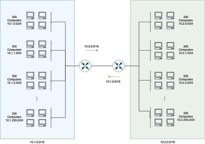
I thought about 2 examples. One is hierarchical routing inside a LAN.
This example is very simple:
- We allocated IPs in a hierarchical way (a /16 for each site), so each router only needs to know its local routes and the aggregated routing to the other site.
- As a result, we have much less routes on the route tables (257 routes - 256 local + 1 aggregated - instead of 512).
- Note: I’m ignoring the point-to-point network between the 2 routers.
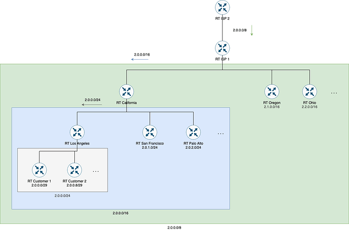
The other example is hierarchical routing into a WAN - ISP network spread across the country. Here the ISP allocate IPs in a hierarchical way, so route tables will be very small. The peering between ISPs will be simplified as well (the other ISP can use a single aggregated route to reach our ISP, it doesn’t need to have individual routes for each small network.
Some info:
- RT California doesn’t need to have a route for each small /29 network for each city. Only a single route for each city is necessary (/24).
- RT ISP 1 doesn’t need to have a route for each small /29 network as well. It doesn’t even need to have routes for each city (/24). Instead, it can have a bigger route for each state (/16 in the example)
- RT ISP 2 doesn’t need to learn every small route (/29) that exist in ISP 1. Instead it can only have a single big route to RT ISP 1 (/8).
If you thing it’s worth to add hierarchical routing in the lesson, fell free to use my examples as an starting point. Anyway, I’ll keep the examples here, so they may be used as complementary learning material for new students using the forum.
Hello Rarylson
Thanks so much for sharing your thoughts and ideas. Yes indeed routing offers a hierarchical structure to the way packets are forwarded among routers, and your examples are helpful in getting that message across.
The hierarchical nature of IP addressing is addressed in the subnetting lesson, while the specific feature that helps to keep routing tables smaller is route summarization.
Thanks again for sharing!
Laz
Hi Lazaros,
The hierarchical nature of IP addressing is addressed in the subnetting lesson, while the specific feature that helps to keep routing tables smaller is route summarization.
I read the lessons, and I agree that the subjects subnetting/summarization are there. But my intention with my previous suggestion was not to discuss the technical definitions, how to split prefixes, etc. This is important (especially for Cisco certifications), but the definitions (only) do not explain why hierarchical IP allocation is important and what are the design principles behind it.
Instead, I was proposing to explain (using examples) that IP was built to be hierarchical by design. On the Internet, IP allocation is hierarchical. And this is a great advantage over switching when thinking about scalability.
I think it’s worth to introduce the design/architecture concepts regarding hierarchical routing, with good examples, as soon as possible. And I think this first introductory lesson is the ideal place to put that explanation (if not, in another and independent lesson). So people will start to understand this important concept.
My idea is just to introduce the concept of hierarchical routing with one or two examples and explain why it’s good and its advantages over switching. Not just having the definitions of subnetting/summarization.
Side note: Lesson Introduction to Route Summarization is great! You did a great job explaining advantages like summarization saves CPU cycles. But lesson focus on the feature, and although explain advantages, doesn’t demonstrate that IP was built with hierarchical routing in mind, doesn’t provide examples that shows that Internet works this way (hierarchical routing, with bigger routes at borders, and smaller routes closer to “final users”), and doesn’t explain that Internet is possible only because routes are hierarchical. So, although lesson is great, I still think you would add a lot of value introducing the concept of hierarchical routing with one or two examples, and explaining why it’s important and it’s a basic IP principle.
----
Side notes:
In practice, lots of people don’t understand this (they understand summarization as a feature, but they do not necessarily comprehending why it’s important and why it should be used) and do not plan networks with hierarchical routing in mind. What I see in practice is lots of /24 networks being allocated without any criteria, making impossible to aggregate afterwards, and generating a lot of scalability problems due to huge routing tables (or cost problems, because now every router needs to be big/expensive in order to process the big route tables).
Even talking about BGP, usually I have to explain people that there is a very good reason why BGP requires routes to be at minimum /24, and that it doesn’t mean that you must only use /24 (if you can summarize to /20 or /21, you should).
Hello Rarylson
Thanks so much for taking the time to share your thoughts. I will let Rene know to take a look and consider your suggestions. Thanks again!
Laz


