Introduction to Spanning-Tree

Hi Mr. Rene,

If I have a system of switches and in that system, I have 2 switches, with 2 links between them. Switch 1 has a lower MAC address as compared to switch 2. Both the switches have the same priority value, the links have the same cost. Then the lower port number on the switches get higher priority. In case, I want to specify a specific port as a designated port as in if I want the higher port number as my designated port, how will I do that?

Hello Divya

Since SW1 has a lower MAC address, it will become the root bridge. This means that both of its ports will be forwarding. SW2 will have one of its ports in blocking state and one forwarding. Specifically, as you suggested, the port with the higher priority value (the lower port number). Now the port priority is composed of the priority (the default is 128) a dot and then a number, which corresponds to the physical port of the device. The numbering depends on the platform and the number of ports. So a priority may appear as 128.14 for example. Higher port numbers will have higher numbers after the dot, while the 128 is the same for all ports by default. If you want to increase the priority of a particular port, you change the default value of 128 to something smaller.

So in your example, if the ports being used on SW2 are FastEthernet 5 and 6, then their default priorities may be 128.5 and 128.6. FastEthernet 5 will be in a forwarding state and 6 will be blocked.

You can change the default priority using the following command:

Switch(config-if)# spanning-tree port-priority 112

For priority, the range is 0 to 240, in increments of 16. Thus valid values are 0, 16, 32, 48, 64, 80, 96, 112, 128, 144, 160, 176, 192, 208, 224, and 240. All other values are rejected. The above command applied to FastEthernet 6 would make it forward and port 5 blocked.

I hope this has been helpful!

Laz

Hi Rene and staff,
i suggest it would be better in the lesson to say
Bridge ID = Priority + MAC address
and not
Bridge ID = MAC address + Priority
because priority is evaluated first, is not it ?


Regards

Hello Dominique,

I agree, that is a good change. Priority is evaluated before MAC address so it makes sense to mention it first. I just fixed this. Thanks!

Rene

Hi! I am wondering why on the show spanning-tree output for sw1 interface Fa0/14 is a designated port? Switch 1 is a non-root bridge. I thought designated ports were only on the root bridge? Thanks for your help!!

Hello Connie

Not quite, but almost!! Root bridges have ONLY designated ports. That is to say that all ports on a root bridge are designated ports. There are no root or blocked ports on a root bridge. However, non-root bridges also have designated ports. Any ports that are not root ports and are not blocked are designated ports. In this case, SW3 is the root bridge, therefore Fa0/17 on SW1 is the root port, and since Fa 0/14 is not blocked, it can only be designated.

I hope this has been helpful.

Laz

Hi,

I have question.
Three switches connected in triangle manner.I have disabled spanning tree on all the three siwtches.
Now I see log message on of the switch console saying “mac address flapping” .
How to T SHOOT this scenario to find out the machine tats trying to send data ???

Thanks in advance

Hello Ajai

MAC address flapping is a symptom of the problem that you have simulated by creating a Layer 2 loop. The SYSLOG message that you see should include the MAC address in question as well as the interfaces between which they are flapping. You should see something like this:

Oct 3 12:49:05.656: %SW_MATM-4-MACFLAP_NOTIF: Host f04d.a206.7fd6 in vlan 1 is flapping between port Gi0/16 and port Gi0/5

So right away, you can see the ports that the flapping is occurring on. You can then go to a host on the network (or on one of the switches) and examine the ARP table to see the IP of the host whose MAC address is flapping.

In any case, the resolution to such a problem in a production network is always to remove the Layer 2 loop. The cause of the problem is the loop itself and not the host whose MAC address is flapping. Even if you determine which machine it is, the problem is still there until you resolve the loop.

Keep in mind that the MAC address may be of one of the switches as well and not necessarily a host connected to the switches.

I hope this has been helpful!

Laz

1 Like

Hello Laz,
i read in a cisco doc that the command to find if a switch is a root bridge is :
show running-config | include root

but, in my opinion, i think
show spanning-tree | include root
or
show running-config | include priority

I test on packet tracer that a “root primary” command creat only “spanning-tree vlan 1 priority 28672” which is sufficient to be root… until “root primary” is set, after some time, on an other switch. then “show running-config | include root” never work.
Am I right ? Is it a packet tracer mistake ?

or at contrary does a cisco ios show the word “root” in the show run command of a root bridge switch for at least one vlan ?

Hello Roger,
you are right that “show running-config | include root” is not going to show you anything, because there is not root keyword in running-config.

On the other hand “show spanning-tree | include root” is better approach, it is going to show you if switch is root for any of vlans. We can tweak it a bit more, so the output is going to show you for which vlan it is root.

SW1# show spanning-tree | include root|VLAN
VLAN0001
VLAN0010
             This bridge is the root
VLAN0020
VLAN0030
VLAN0040

By using additional “|VLAN” output includes also all lines with “VLAN” in it, so it can give you overview for which VLAN it is the root.

The command “show running-config | include priority” is going to give you vlan number and local switch priority, however, it does not guarantee that with this whatever priority switch is the root.

The best command to show you the root is probably this one.

SW1# show spanning-tree root
                                        Root    Hello Max Fwd
Vlan                   Root ID          Cost    Time  Age Dly  Root Port
---------------- -------------------- --------- ----- --- ---  ------------
VLAN0001         32769 0c00.b82b.c100         4    2   20  15  Gi0/1
VLAN0010         24586 0c00.b8fc.7a00         0    2   20  15
VLAN0020         24596 0c00.b82b.c100         4    2   20  15  Gi0/1
VLAN0030         24606 0c00.b86d.3000         4    2   20  15  Gi0/2
VLAN0040         24616 0c00.b8c1.8300         4    2   20  15  Gi0/3

From this command output we can recognize that local SW1 is the root for vlan 10, because it is advertising Root Cost of 0 and does not have a Root Port. Root switches have only designated ports for the specific vlan(s) they are root for.

“show spanning-tree root” is probably not supported on Packet Tracer, but you can give it a try.
You may also note that using pipe “|” for filtering output is most likely not going to be supported in Cisco exam simulations. If you cannot use pipe and “show spanning-tree root” command, the best bet is to use old school “show spanning-tree” or “show spanning-tree vlan #number” command. Or may be “show spanning-tree summary”, in our case it is telling us that local switch is root bridge for vlan 10.

SW1# show spanning-tree summary
Switch is in rapid-pvst mode
Root bridge for: VLAN0010
Extended system ID                      is enabled
Portfast Default                        is disabled
Portfast Edge BPDU Guard Default        is disabled
Portfast Edge BPDU Filter Default       is disabled
Loopguard Default                       is disabled
PVST Simulation Default                 is enabled but inactive in rapid-pvst mode
Bridge Assurance                        is enabled
EtherChannel misconfig guard            is enabled
Configured Pathcost method used is short
UplinkFast                              is disabled
BackboneFast                            is disabled

Name                   Blocking Listening Learning Forwarding STP Active
---------------------- -------- --------- -------- ---------- ----------
VLAN0001                     2         0        0         14         16
VLAN0010                     0         0        0          3          3
VLAN0020                     2         0        0          1          3
VLAN0030                     2         0        0          1          3
VLAN0040                     2         0        0          1          3
5 vlans                      8         0        0         20         28

Regarding to command “spanning-tree vlan #number root primary/secondary”, in reality this is not a command, but it calls macro that tries to set switchs priority.

If you use “spanning-tree vlan #number root secondary”. It sets the priority for specific vlan to 28672. This number is not dynamic, it always has base of 28672. It is because only BPDU from root bridge is propagated, thus we dont know what is second best priority, therefore we set default priority 32768 minus 4096 which equals to 28672.

If you use “spanning-tree vlan #number root primary”. This macro is trying to set your switchs priority dynamically to become the root for specific vlan. Priority here always starts with base of 24576 (= 32768 – 2 * 4096) and can go dynamically lower if needed. Remember that this macro is not able to make the switch root in case current root already has priority of 0 or 4096.

Because “root primary/secondary” is not a command, but a macro, we cannot see it in running-config as a command. We can see only priority for certain vlans that may be or may be not, were set by these macros.

2 Likes

thanks,
i got it
do you think that

Blockquote
SW1# show spanning-tree | include root|VLAN
creat the same result as
Blockquote
SW1# show spanning-tree | include VLAN|root
?

Yes, output is going to be the same, we can exchange order of keywords.

Imagine second pipe “|” like there is an “or” instead.
We want to include only lines, that contain VLAN “or” root.

ok, thanks
by the way, as I named my VLANs, the command

Blockquote
show sp sum

only show the name of the vlan, and not its number:
for example :

Blockquote
SW2>show sp sum
Switch is in pvst mode
Root bridge for: default

and I have to translate default=VLAN001

Hello all,
Is it possible to have, behind the same router(s), some switch in pvst mode, others in pvst+ mode and others in rapid pvst mode (even ii is not a best practice) ? or, at the opposite, is it mandatory to keep the same standard of spanning tree for all the switches because well knows issues could come ?

Hello Hugues

Just to clarify, PVST is a spanning tree protocol that uses CIsco’s ISL trunking encapsulation, and is incompatible with IEEE 802.1Q tagging. PVST+ is an enhancement to PVST that allows it to function over 802.1Q trunks as well. Rapid PVST+ is simply an enhancement to PVST+ that allows for faster convergence.

Now in most recent Cisco platforms you won’t find plain PVST as an option unless you have a really old switch, and unless you are using ISL trunks (which is unlikely in modern networks), so it would be difficult to achieve this. PVST+ is backward compatible with PVST, so in theory you can have both running, but PVST must run only in an ISL environment. Now PVST+ and Rapid PVST+ essentially are based on STP IEEE802.1D and IEEE 802.1w respectively. Rapid PVST+ is backward compatible with PVST+, and when you require backward compatibility, Rapid PVST+ essentially behaves like PVST+, so it’s as if it doesn’t exist.

So to answer your question, yes it is possible, but PVST can only run in regions of your network using ISL trunks, and Rapid PVST+ will have to operate as PVST+ wherever it encounters it on the network.

I hope this has been helpful!

Laz

thanks, I got it.
I think that packet tracer is actually not sufficient to STP for ICND2 : i will download GNS3 to make my own lab for STP

1 Like

I don’t get any immediate screen output from the debug spanning-tree events commands showing changes when I plug a host into the switch. Disabled spanning globally - no spanning tree default. I do see the number of topology changes when I do sh spanning-tree detail. Switch model is WS-C3560-48TS. Not sure what I am missing.

Hello Donald

Take a look at this Cisco documentation on troubleshooting spanning-tree. It should give you a starting point from which you can continue your troubleshooting.


When attempting to see debug output, make sure that the changes you are making to the topology do indeed constitute changes that would cause STP to reconverge. If you have any additional issues, share your topology with us so we can further assist.

I hope this has been helpful!

Laz

Hi Rene,
I really don’t understand the logic, Please elaborate…how will the blocking move through states, if it starts to receive the BPDU

Hello Abilash

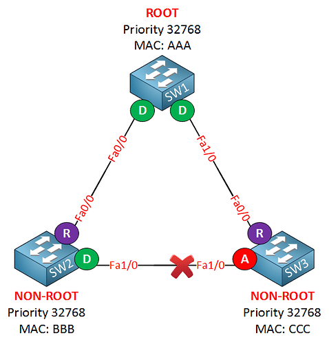
If you have three switches connected to each other like so:


STP, after converging, decides to block the Fa1/0 port on SW3. Now BPDUs are being sent from the root bridge to the other switches, and these propagate throughout the topology, and they also reach this blocked port.

Now if you go into SW2 and issue the spanning-tree bpdufilter enable command on Fa1/0, you will essentially stop all BDPUs from exiting this interface. This means that Fa1/0 on SW3 (the blocked port) will stop receiving BPDUs, and will thus begin to move through the states. It is the stoppage of BPDUs to the blocked port that triggers it to begin moving through the states, eventually entering the forwarding state.

I hope this has been helpful!

Laz