I made a change because it had an error. DSW1 and DSW2 should use a dynamic method to establish a trunk. DSW1 should do this actively, DSW2 passive. It has been fixed. Thanks!
Rene
I made a change because it had an error. DSW1 and DSW2 should use a dynamic method to establish a trunk. DSW1 should do this actively, DSW2 passive. It has been fixed. Thanks!
Rene
Thanks, I just fixed this.
It’s been a year since I posted this, but I now have two mini PCs with AMD Ryzen 9 CPUs 8c/16t and 64GB of DDR5 RAM. I have Proxmox installed on them. In Proxmox, I have three VM containers with CML 2.8 and 2.9 and GNS3 (the latest version). I haven’t had any resource issues since.
Hello Michael
Nice to hear from you again! That’s good news, thanks for sharing that with us. The setup of your hardware for emulation plays a major role in the performance of the topology you create. Thanks again for sharing
Laz
Hello Rene, Laz,
Dynamic method to negotiate trunks is not recommended by Cisco. Cisco suggests manually configuring trunk links to avoid potential misconfigurations and security issues that can arise from automatic negotiation. I think this point should not be proposed in a lab like this and instead use manually configured trunk links. Best regards Michael.
Furthermore I am asking myself why spanning-tree is never applied to vlan 1. It’s normal business to set the priority higher then the others to prevent VLAN 1 becoming a root bridge.
spanning-tree mode rapid-pvst
spanning-tree extend system-id
spanning-tree vlan 1 priority 61440
spanning-tree vlan 1,10,20,30 priority 4096
spanning-tree vlan 10 hello-time 3
spanning-tree vlan 10 forward-time 10Hello Michael
Indeed, Cisco recommends completely disabling the use of DTP when creating trunks. The purpose however of the lab is to allow users to experiment with the capabilities that exist, so that if they discover some strange behavior, they will be able to identify it as behavior due to the use of DTP.
Having said that, it is useful to indicate clearly that it is best practice to disable DTP. I will let Rene know to take a look and consider making any changes…
I hope this has been helpful!
Laz
Hello Laz, Rene, I see that I made a mistake the priority should be lower of course 61440 is the lowest priority and 0 the highest priority but de lowest value and 61440 is the highest value. I guess I am a little confused with the labels because of the selection of a DR/BDR routers where it the other way around. VLAN 1 participates in rapid SPT, just as the other vlans but in theory VLAN 1 can become the root bridge right? To prevent this you should set it to the value of 61440 which is the highest value but lowest priority. What do you advice?
Hello Michael
I didn’t see the next section you added to your original post, I’ll address that now:
If you take a look at the 4.2.4.2 Primary and Secondary Root of the lab, you’ll see that STP is applied to VLAN 1 as well, and a priority of 0 is set for DSW1 for all VLANs. In any case, priority settings can be confusing especially when OSPF DR/BDR priority settings work the opposite way!!
You can indeed configure a switch to become the root or to not become the root for any particular VLAN, including VLAN 1. Now, whether you want to do that or not depends on the topology and the specific VLANs in question. For this particular lab, the DSW1 switch is configured with a priority of 0 (highest priority) to become the root bridge for all VLANs, including VLAN 1, and that’s perfectly valid. Unless you have specific requirements, this setup is fine as it is.
I hope this has been helpful!
Laz
Thank you Laz clear as always.
Best regards, Michael
Hello Laz, Rootguard is even a better solution and more reliable then setting a priority of 0 or 61440 (vlan 1). Do you agree?
Best regards,
Michael
Hello Michael
You are correct, it is possible to use Rootguard to achieve something similar, but you have to keep in mind that Rootguard and the setting of the bridge priority are two different features that solve two different problems.
The priority value is the feature that you should use to deliberately set the root bridge in your topology. By configuring the priority appropriately in all switches, you can cause a specific switch to become the root.
The Rootguard feature however is used on ports where you NEVER want a superior BPDU. This should be done on access ports and edge facing ports. This protects against users plugging in “rogue” switches on ports where switches should never be plugged in, and messing up your choice of root bridge!
Rootguard should never be put on links that could legitimately become a root port, such as switch uplinks. During a failure, this can cause a potential backup link to stay down!
So Rootguard isn’t more reliable than setting the priority, but it works in a complementary manner. You should set priorities in the core while enforcing boundaries with Rootguard at the edge. Does that make sense?
I hope this has been helpful!
Laz
Thanks Laz! Really appreciate your clear explanations.
Best regards,
Michael
Is it possible to synchronize the configurations with the configurations in the overview because they don’t match? It’s very difficult to verify. I really don’t understand why they should differ. Could this be adjusted, please? Frankly, I think it’s sloppy that this still hasn’t been done.
I solved it with a few OSPF statements on DSW1 and DSW2 . I advertised the vlans. No SVI needed on ASW1 and ASW2, no default gateway. No OSPF advertisements. It ‘s working flawless. Clients received the correct IP addresses and can ping everything. I used subnet 172.31.0.0 /16 for the lab. And static trunks between the DSW and ASW switches. No dynamic trunks. Cisco states they are unreliable in production environments.
Hello Michael
Thanks for your feedback. Can you clarify what is missing or out of sync? Do you mean that the startup configs in the lab only show the ISP router? Or do you mean the final configs at the end? Can you show us where they don’t match so we can fix it as soon as possible?
Thanks!
Laz
Hello Laz,
Let me start by saying that I’m very satisfied with the Networklessons website. I haven’t found a better website yet. This one truly stands out.
Returning to your question, I’ve tried to create this lab several times: https://networklessons.com/labs/network-fundamentals-lab-1. It’s a great lab to practice with. However, I have a few issues I’m struggling with.
First, the combination of IPV4 and IPV6 in one lab. I’ve separated both labs and the information that is all on one webpage. So, I actually have two labs: an IPV4 and an IPV6 lab. I found it confusing having all the information listed one below the other. I was constantly scrolling. That’s why I decided to separate the two and create two labs.
Furthermore, I struggled for a long time with getting the host PCs to obtain an IP address via DHCP. The part about the ASW switches, in particular, isn’t clear to me yet. There were some comments about it in the forum: Network Fundamentals Lab 1 - #7 by lagapidis. Options were discussed, such as enabling OSPF on the ASW switches and DSW, and creating an SVI on the ASW switches with a default gateway. However, I don’t see this reflected in the lab or in the final running configurations.
When creating the lab, I only created an OSPF2 statement on the DSW switches with VLANs 10, 20, and 40. I ignored VLAN 30. However, I don’t see it reflected in the final running configurations. I personally didn’t need an SVI interface or gateway on the ASW switches. I created VLANs 10, 20, 30, and 40 on the ASW switches and configured the access ports. I used purely L2 configurations. And that’s sufficient because the routing takes place on the DSW switches via VRRP and the SVIs via the static trunks (allowed vlan 10,20,40).
Furthermore, I find the choice of OSPFV3 a bit unfortunate in combination with IPV4. It makes things a bit more unclear. CCNA (as far as I know) doesn’t mention OSPFV3 in combination with IPV4. For example, see the example below:
CSW2#show ipv6 ospf neighbor

OSPFv3 Router with ID (10.0.128.3) (Process ID 1)

Neighbor ID Pri State Dead Time Interface ID Interface
10.0.128.2 1 FULL/BDR 00:00:35 13 Port-channel1
10.0.128.4 1 FULL/BDR 00:00:39 15 GigabitEthernet0/3
10.0.128.5 1 FULL/BDR 00:00:36 14 GigabitEthernet0/2
10.0.128.1 1 FULL/DR 00:00:36 3 GigabitEthernet1/0
Why is it written “show ipv6 ospf neighbor” here? The official documentation describes it differently: https://www.ciscopress.com/articles/article.asp?p=3188198&seqNum=5
This command should be used with IPV4.
The rest of the lab, I find the lab very clear. However, I can’t understand everything I see in the lab from the perspective of IPV4 and IPV6 in combination with OSPFv3. I think there are some incorrect descriptions.
Finally, I find the section about the ASW switches a bit confusing in some places. An IPv6 statement is made somewhere in the lab, but I don’t see it reflected in the running configurations (perhaps I didn’t look at it or understand it properly).
ASW1:
ASW1(config)#ipv6 router ospf 1
ASW1(config-rtr)#router-id 10.0.128.6

ASW1(config)#interface Vlan 40
ASW1(config-if)#ipv6 ospf 1 area 0

ASW1(config)#interface Loopback 0
ASW1(config-if)#ipv6 ospf 1 area 0
ASW2:
ASW2(config)#ipv6 router ospf 1
ASW2(config-rtr)#router-id 10.0.128.7
ASW2(config-rtr)#interface vlan 40
ASW2(config-if)#ipv6 ospf 1 area 0
ASW2(config)#interface Loopback 0
ASW2(config-if)#ipv6 ospf 1 area 0
My conclusion, therefore, is that I find the configurations and solutions offered for the ASW switches particularly unclear. My solution worked fine, but I don’t see this reflected in the lab.
Best regards,
Michael
Hello Michael
Thanks for sharing your progress on this. It’s great that you’re experimenting and are tweaking the lab to make it perform as you desire, and that’s part of learning and getting better at networking.
Keep in mind that the lab requirements are specific, and in real-world production networks, there are always specific requirements that you must adhere to. You may be able to do it differently, but it won’t be acceptable if it is not within the requirements.
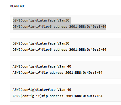
The specific requirements for the lab were that ASW1 and ASW2 have an IP address on the VLAN 40 subnet, which is the management VLAN. It also says that all VLANs, all point-to-point links, and all loopback interfaces must be reachable.
That means that ASW1 and ASW2 must have a single SVI configured on each for VLAN 40 with the addresses stated in the lesson. Also, the loopback addresses must be reachable, so you have to advertise them somehow. That’s why ASW1 and ASW2 must have OSPF configured (or you can put in static routes everywhere to those loopbacks, but that’s not practical!)
So your clients may work as you say, but the requirements are not being fulfilled.
You’re absolutely right, statically configured trunks are always the way to go! However, the requirements stated that:
- The access layer switches should use a dynamic method to negotiate the trunk link.
- The distribution layer switches should use a static method to create a trunk.
So even though it’s not best practice, it was asked for specifically for the access layer switches.
I hope this has been helpful!
Laz
Hello Laz,
Thanks for your reply.
I think it is a good idea to verify the end configs and compare them with the actual lab descriptions there are some anomalies.
And my recommendation is to separate ipv6 from ipv4. There are things not right see my comments. Rene makes statements which are not correct strictly speaking. See the link to the cisco website.
Best regards,
Michael
Hello Laz,
I do not agree with your statement that access
switches should have ospf statements on the management vlan 40. In our company this is not allowed. We call it OOB (out of band) and they are strictly separated from the production network.
Access switches should not participate in OSPF areas. They should be stricttly L2 switches. Routing should be done on the distribution layer and above.
In the lab Rene configured IPV6 interfaces on the access switches. I don’t see this back in the running configs.
The part of the access switches is the most unclear part of the whole lab.
Best regards,
Michael