Even if the receiving port is not the root port of the switch?
Hello Thierno
Yes, even if the receiving port is not the root port of the switch. All ports maintain a “distance to the root bridge” so that they can be compared. It is the port with the smallest cumulative distance to the root bridge that becomes the root port. If the topology changes, and these values change on the ports, new roles are assigned and the root port can and does change to a new port.
I hope this has been helpful!
Laz
Hi Rene and staff,
port priority of a upstream SW port is send to a downstream SW port in the column “Port Identifier” in a config BPDU. Am i right ?
Port ID is 2 bytes like this
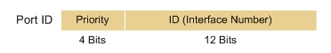
Let’s take an example

In this example, Port ID is 0x8001
Looking at the binary format (4 + 12) suggest that port-priority should be multiple of 16 (with 4 bits you could have 128,64,32,16)
But i read in this documentation
“Port priority value. The range is from 1 to 224, in increments of 32”
So i wonder why port-priority is not in increments of 16 (?)
Could you help me to understand ?
Regards
Hello Dominique
On Cisco IOS platforms, the port priority values are indeed between 0 and 240 in increments of 16. On Nexus platforms, such as is the case with the link that you provided, the range is between 0 and 224 in increments of 32.
The port ID in the BPDU as you mention will have 4 bits for the priority and 12 bits for the interface number. 4 bits allows you to to have values between 0 and 240 at increments of 16 because that’s (0 16 32 48 64 80 96 112 128 144 160 176 192 208 224 240) 16 values which can indeed be represented using 4 bits. Now if we look at the range provided on the Nexus platforms we get (0 32 34 96 128 160 192 224) which is eight values, which can be represented using 3 bits.
Now I was unable to find a definitive answer as to why this is the case, but this is my assumption. Because Nexus switches are made to be more scalable than IOS switches, the number of ports on a particular device may be very great. This required that the split of 4 bits priority and 12 bits interface number be redefined as 3 bits priority and 13 bits interface number, so that more interfaces can be represented. So for communication between nexus switches, this split has been adopted, resulting in fewer priority values, but more interface values.
This is backward compatible with other switches using the 4/12 split since only values with increments of 32 are being used.
I hope this has been helpful!
Laz
Hi Laz,
great, thank you very much
Regards
1 Like
Hello guys,
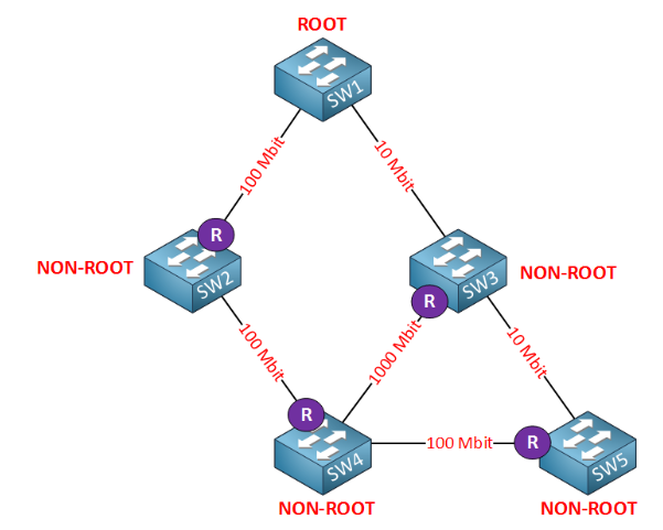
I am reviewing STP and I really liked this explanation, however on this example, I was a little bit uneasy with the review of the Designated Ports, because on this particular instance, SW3’s port that is facing SW1(the root) is not preferred as the root port path, but the SW3’s port that is facing SW4. This part is ok with me, until I realize that all the ports int the root would not be designated ports because SW3 is preferring the path towards SW4? Maybe I dont have the whole story straight? Can someone please clarify. Thanks!
Hello Martha
Remember that the root port on each non-root switch is chosen based on the cumulative cost to reach the root bridge from that particular port. Because the link between SW1 and SW3 is at 10 Mbit, it has a cost of 100 where the total cost via SW4 is 42, as described in the lesson. From your post, I think you’ve understood this part, but I just wanted to establish the reason for the choice.
Now by definition, all the ports on the root bridge (SW1) are designated ports. This is the case regardless of what state the the ports on the remote end of each link are. So the 10 Mbit port on SW3 connected to SW1 may be designated or even blocked, but that doesn’t affect the state of the ports on the root bridge.
In general, the state of the port on the remote side of a link does not affect the state of the local port on the link. It is only the location of the root bridge and the cost to the root bridge that affect those states.
I hope this has been helpful!
Laz
1 Like
thank you so much for your prompt responses.
Hello,
Looking at the Spanning Tree Cost Calculation Page, it says:
SW3 will forward BPDUs to SW4. The root path cost field will be 100.
SW4 receives a BPDU from SW2 with a root path cost of 19.
SW4 receives a BPDU from SW3 with a root path cost of 100.
Shouldn’t the root path cost from Sw3 to Sw4 be “4” since its a 1000 mbps link?
Thanks for any clarification to assist my understanding.
Chris
Hello Chris
When a switch sends a BPDU to its neighbors, the value of the cost field will not be that which corresponds to the interface from which the BPDU was sent, but it corresponds to the cost of the most direct route (physically) to the root bridge. For SW3 that is the 10Mbps connection to SW1. So think of the value in the cost field of a BPDU as an announcement by each switch to the rest of the world of the cost to the root bridge (not the best cost, but that of the most direct route). So SW3 is saying “my path to the root bridge costs 100!” SW4 is announcing “My path to the root bridge costs 38!” So SW3 then says, “OK, your path is better, I’ll make my port to you be my root port”.
If SW3 had said my cost is 4 because of the speed of the link with SW4, then SW4 would make it’s connection to SW3 the root port. You can quickly see that this doesn’t work.
Switches use the BPDUs to compare costs to the root bridge to decide which ports will become root ports.
I hope this has been helpful!
Laz
1 Like
Where it says:
This picture needs some more explanation so let me break it down:
SW3 will receive BPDUs on its 10 Mbit interface (cost 100) and on its 1000 Mbit interface (cost 4). It will use its 1000 Mbit interface as its root port.
Shouldn’t the Root Path Cost Field coming from SW4 to SW3 be 42 rather than 4?
Hello Martha
Yes, you are correct that the cost that SW3 will receive in BPDUs on it’s GE port will indeed be 19+19+4=42, however I believe that Rene is referring just to the cost of the GE interface. Even so, the statement may be misleading, so I will let @ReneMolenaar know to look at it and clarify the statement.
Thanks for pointing that out!
Laz
Hello Rene,
Thanks for this lesson,
I have a question:
what is the cost for the link between SW1 and SW2 if we assume Switch 1 has Fast Ethernet port and SW2 has Giga Ethernet port? will it be 4 or 19.
Thanks in advance
Hello Wisam
The cost of a link that is calculated by STP corresponds to the actual speed at which the ports are functioning. If you have a GE port connected to an FE port, then that link will function at 100 Mbps. The resulting STP cost will be that which corresponds to 100 Mbps which is 19.
I hope this has been helpful!
Laz
Laz, can you say if this is correct:
ELECTING THE ROOT Bridge
Lowest Bridge ID
- Priority value
- MAC Address
ELECTING THE ROOT PORT
The lowest Cost to reach the root bridge
The lowest neighbor bridge ID
The lowest neighbor port priority
The lowest neighbor advertised port number
DESIGNATED REDUNDANT LINKS
The lowest Cost to reach the root bridge
The lowest neighbor bridge ID
The lowest neighbor port priority
The lowest neighbor advertised port number
LINKS TO MULTIPLE DESIGNATED SWITCHES
The lowest Cost to reach the root bridge
The lowest neighbor bridge ID
The lowest neighbor port priority
The lowest neighbor advertised port number
1 Like
Hello Dinesh
Yes, this looks correct. You can find out more information about all of this in the following lesson:
I hope this has been helpful!
Laz
1 Like
Hi Laz,
For electing the root bridge and root port, since the MAC address is used as a determining factor, shouldn’t the election finish right there since no two MAC address can be the same:
ELECTING THE ROOT PORT
The lowest Cost to reach the root bridge
The lowest neighbor bridge ID
The lowest neighbor port priority
The lowest neighbor advertised port number
So the last two options shouldn’t be required, unless there are redundant links to the same switch
Hello Dinesh
Yes, that is correct. These two tie breakers are used for redundant links between two switches. It is only in that case that you will have the same bridge ID on multiple links.
Now having two switches connected directly with redundant links is rarely a good network design. This is because only one of the links will be active at any one time, while all the others will be blocked. This is an inefficient use of the available bandwidth. Unless you have some extraordinary circumstances where you cannot do otherwise (I can’t really think of any to be honest), if you want to connect two switches with multiple links, you should use Etherchannel, which provides the required redundancy, while using the bandwidth of all available links.
I hope this has been helpful!
Laz
1 Like
Hi Rene/Laz
I am a bit confused as to what a switch inserts into its root path cost field for sending on to the next switch. Is it not the cost of its shortest path to the root bridge? In the first topology we have:
- SW3 receives BPDUs on its 10 Mbit interface (cost 100) and on its 1000 Mbit interface (cost 4). It will use its 1000 Mbit interface as its root port (shortest path to the root bridge is 19+19+4=42).
- SW3 will forward BPDUs to SW4. The root path cost field will be 100.
SW3’s shortest path is through SW4 itself, with a cost of 42, but we are saying here that it will send a root path cost of 100 to SW4, which is the cost corresponding to the 10Mbit connection, the physically most direct route to the root.
Can you clarify?
Thanks,
Phil
Hello Philip
When one switch sends a BPDU to another, it will include information in the root path cost field. The value included in the root path cost field will be the cost of the shortest path to the root excluding that via the interface from which the BPDU has been sent. It’s kind of similar to a split horizon rule, although this term is not used to describe it.
So SW3 has three possible paths to the root switch with these costs:
- cost 100 via direct connection to SW1 (at 10 Mbps)
- cost 19+19+4=42 via SW4–>SW2–>SW1
- cost 100+19+19+19=157 via SW5–>SW4–>SW2–>SW1
Now when SW3 shares BPDUs with the cost values in the cost fields, this occurs:
- When SW3 sends its BPDU to SW5 it will use a cost of 42 which is the best path excluding that of the link to SW5.
- When SW3 sends its BPDU to SW4 it will use a cost of 100 which is the best path excluding that of the link to SW4
- When SW3 sends its BDPU to SW1 it will use a cost of 42 which is the best path excluding the link to SW1
So you see, because the path via SW4 has a cost of 42, that cost cannot be shared with SW4 (split horizon), because if this cost turns out to be the best for SW4 as well, there will be a loop. The link between SW4 and SW3 would then be connected to two root ports, something which should never happen in an STP topology.
I hope this has been helpful!
Laz