Hello ,
Just wanted some clarification on my doubts below
What will be the state of other ports which are unnamed on other switches & how it is decided if it will be Designated or Alternate
Regards
Ziad
Hello ,
Just wanted some clarification on my doubts below
What will be the state of other ports which are unnamed on other switches & how it is decided if it will be Designated or Alternate
Regards
Ziad
Hello Ziad
Here are some general principles that will help to determine the port roles.
With just these two guidelines, we can find out what all the states of the ports in the above diagram will be:
So we get:
Now it was easy to find the blocked ports, because they were the only option in this topology. Larger more complex topologies may require additional calculations to determine these. But you can find out more information about this procedure for normal STP and for RSTP at the following lessons:
I hope this has been helpful!
Laz
Hi ,
I am bit confused with understanding of BDPU processing
As i understand when STP is configured for the first time i.e. root bridge is not elected yet the BDPUs are exchanged by all switches & then once root bridge is selected so what happens after this with regards to BPDUs from root , non-root switches ?
Regards
Shaan
Thank You
Regards
shaan
Hello Ziad
At the beginning, when all switches are turned on, all switches consider themselves root bridges. This means that BPDUs are sent out of all active ports of all switches. When this happens, each switch compares its own priority with the priority it has received from other BPDUs. If it finds a better priority than it has, then it considers the switch from which a better priority BPDU has been received as the root bridge.
As soon as a switch becomes a non-root bridge, it no longer sends BPDUs. In a converged STP topology, only the root bridge sends BPDUs, and non-root bridges will only receive BPDUs on their root ports. When they do, they relay those BPDUs out of all their designated ports until all the switches receive the root bridge’s BPDUs. In a stable topology, the root bridge sends out BPDUs every two seconds.
Until now, we’ve teen talking about control BPDUs, those which are sent under normal STP operation, where the topology is converged. Now there are special types of BPDUs, such as Topology Change Notifications (TCNs) and Topology Change Acknowledgements (TCAs) which are sent when a change in the topology is detected. TCNs are indeed sent by non-root bridges “upstream” towards the root bridge, while TCAs are sent downstream from the root bridge. More about TCNs and TCAs can be found in the following lesson:
I hope this has been helpful!
Laz
Thank you for detailed explanation lag
Regards
Ziad
Hi Rene,
I think you’ve made an error, or perhaps I’ve just misunderstood.
“SW3 will forward BPDUs to SW4. The root path cost field will be 100”
Would the cost not be 4 over the single 1000 Mbit path to SW4?
“SW4 receives a BPDU from SW3 with a root path cost of 100”
This is the same cost miscalculation where you appear to have miss represented the 1000 Mbit path as a 10 Mbit path.
Hello Scott
When a switch sends a BPDU to a neighboring switch with a value for cost, the switch is reporting the cost to the root from its own point of view. So SW3 has a cost to the root of 100 (this is the 10 Mbit connection it has to the root). This is the value that it shares with SW4. SW4 will receive this value in the BPDU, but it will then calculate its own cost for that particular interface by taking the value from SW3 and adding the cost of the link between SW3 and SW4, which will be 100 + 19 = 119.
When a switch receives a BPDU with a cost, it must be the cost as seen from the point of view of the sender. To determine the cost to the root from the interface on which the BPDU was received, a switch simply adds the corresponding cost of that interface to the value it received, to get the total cost to the root from that interface.
I hope this has been helpful!
Laz
Hi, can you explain how did you figure out what port is getting blocked? Because I did understand from the introduction lesson that STP blocks the port with the lowest bridge ID, and we have no information about the bridge ID here, I need some clarification please.
Hello Olivier
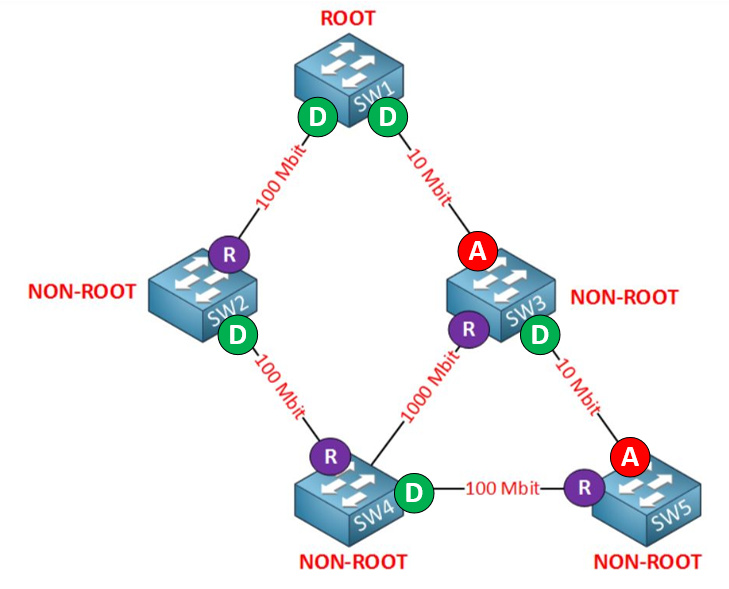
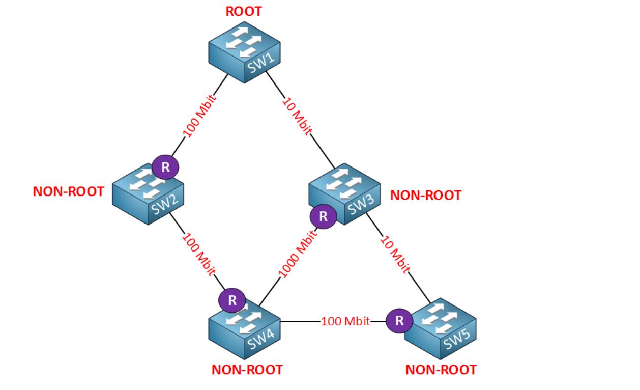
When you look at a diagram like this, the first thing you do is choose the root ports. This is done based on cost, and based on the speeds of the links as they are shown, there is enough information to do so. Now, the next step is to determine which of the remaining ports are designated and which are blocked. Now in order to do this, use the following rules:
After going through the first two rules, we have determined the states of all the ports in the diagram except:
Based on the third rule, it is the SW3 port that goes to SW1 that must be set to blocked because the root bridge cannot have a blocked port.
That means that only the link between SW3 and SW5 remains. The truth is that either of the interfaces on each end of the link can be set to blocked, and this is where we need to use the best bridge ID (as stated in your post as well as in this lesson) to determine which of those two ports will be blocked. So to revise my original answer to the previous post, the diagram looks right as long as the bridge ID of SW3 is lower than SW5. Otherwise, all the rest of the states can be determined with certainty.
I hope this has been helpful!
Laz
thanks Laz for your clear answer
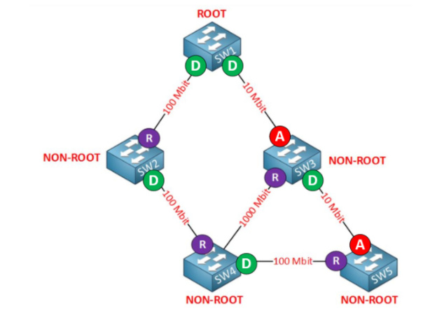
Laz, based on the following screen shot, I did understand how “spanning-tree” works, however, I still did NOT understand how “SW3” selected the “D” port nor the “A” port. No issue with the “R” port.
Also I didn’t understand based on what “S5” selected the “A” port. Please help me out understand this piece of info. Your help is greatly appreciated. Thanks!
Hello Eyad
Imagine for a moment that S5 is not in the topology, and we only have SW1 to SW4. We assume we already know that SW1 is the root bridge. Follow these steps:
After all these steps, all ports have been defined except for the port on SW3. Remember, in order to avoid loops, a blocked port must be introduced. In the above topology, we have a layer 2 loop, and after going through all those steps, in a process of elimination, the only port that can become blocked to avoid that loop is the one on SW3.
Now let’s add SW5 to the topology. Once again:
I hope this has been helpful!
Laz
Thank Laz, I have a better understanding now, however, does this means that If I get/see a topology like this, then I just need to consider a max of four switches like the way you did it? And then add one switch at time to get the final answer? Thanks again for your help!
Hello Eyad
The best thing to do is to begin at the root bridge and work your way outwards. Using this logic, you will be able to determine the states of most ports. Keep in mind that in most cases you won’t need to determine the port states simply from a diagram, you will often have additional information including bridge IDs and priorities as well, which are necessary to be able to get all the port states in a topology.
I hope this has been helpful!
Laz
Excellent. You guys are doing a GREAT JOB!!! I really appreciate that.
Hi Laz,
Kindly let me know the Designated port and Non-Designated ports for given topology where we are using 5 switches?
Hello Pradyumna
I’m not sure which topology you mean, I assume you mean the one in the lesson. This topology already shows where the designated, root, and blocked ports are. You can also see it in this post:
Can you clarify your question so we can help answer it?
I hope this has been helpful!
Laz
Thanks a lot laz understood.
While reviewing the spanning tree root bridge lesson. I connected to the lab to see which of three switches were the root ridge (SW1, SW2, SW3).
Tenda wifi → SW1 → SW2 → SW3
Each switch has a single trunk link between them. To my surprise the port cost was over 1000. Each switch was showing the Tenda Wifi as the root bridge. I disconnected the Tenda wifi and the port cost dropped to 19. Connected it back and the port cost was over 1000 again. Can you refer me to a document that might explain why this is?