This topic is to discuss the following lesson:
in the firs case…obviously you chanded the cost…because is more right…but to get the same thing I can change the priority of the por E0/13…or the priority of the port in switch A Fa0/17??
Hi Francesco,
You could achieve the same by changing the priority. Make sure you do this on the upstream switch though (Switch A and interface Fa0/17).
Rene
I had a question in the interview actually.
I have 3 Switches configured in the circle.
Switch 1 — 2 ----3
All Switches have 100 and 200 VLANs.
Switch 1 is root bridge for VLAN 100
After some time Switch 3 became root bridge for VLAN 100. Priority doesn’t change and no config changed.
SO what could be the other reasons can cause this?
Thank you in Advance.
Hi Ronak,
It’s the bridge ID that determines which switch will become the root bridge. The bridge ID consists of a priority and MAC address.
If the configuration didn’t change then probably the only thing that could have occurred is that one of the links went down. When SW3 doesn’t receiver superior BPDUs anymore, it can become the new root bridge.
Rene
SWITCHA ============ SWITCHB
We have 2 links, 1 link for ISP1 and 1 link for ISP 2
link of ISP2 is bundled on a port channel mode active, the link on ISP is just on a trunk port.
Question:
Will we experience a loop on that setup? one link in a portchannel bundle and 1 link that is not on port channel but on trunk port only.
Thank you.
Hi Don,
If you use mode active then you are using LACP which is safe. The switch will try to negotiate and when it fails, no etherchannel is formed. Since your ISP has regular trunks, nothing will happen.
When you use mode “on” (no negotation) then you have a potential loop.
Rene
Great Stuff!
Hi Rene,
The port priority have to change on upstream switch ?? why not in local switch ??
br//
zaman
Hi Mohammad,
I used to wonder the same thing too. The reason has to do with flexibility and administrative control. As you said, port priority is used by an upstream switch to influence which port a downstream switch will use as a root port. The downstream switch already has a property it can use to determine the root port – the port cost.
Since the downstream switch already has a port property to use on its own (cost), it makes more sense to have the ability for an upstream switch to signal to a downstream switch which port it prefers to be used. This is why port priority is set by the upstream switch.
Why does the Root switch has the port Fa0/17 Blocked in the example “Spanning-Tree Disabled”?
Isn’t that said, that all ports of the root switch should be designated?
If we disable spanning-tree on SW3 (for VLAN 10), then I guess the SW3 should be transparent for spanning-tree: as if the SW1 would be connected directly with SW2 on all four ports.
Hello Lukasz
The diagram that you are referring to indicates that port Fa0/17 is a backup port. This is a port role that is available on RSTP (802.1w). It is one of the two types of port roles that exist for the blocking state. So yes, in essence, this port is in a blocking state.
However, keep in mind that since SW3 does not have spanning-tree activated, as mentioned in the lesson, the STP topology has not converged. A root bridge will have all designated ports once the topology has converged. So essentially, STP root bridge selection has not been completed.
All of the above is the case ONLY for VLAN 10. SW1 can still receive BPDUs from SW3 however, none for VLAN 10. Remember that all of these links are trunks, and we can see that both VLAN 1 and 10 are allowed on the trunks.
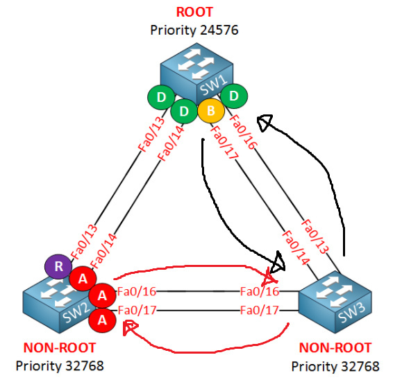
It is important to note that if STP is disabled on SW3, the switch wouldn’t function as being transparent for STP. It would create two layer 2 loops as shown in black and red lines in the following diagram (it was easier to draw than to explain…):
I hope this has been helpful!
Laz
@Laz - great explanation!
1 Like
Hi Laz,
but should not be the Backup port be an Alternate port then?
I thought backup ports only exists if the switch sees its own BPDUs, which is the case if both ports would be connected to the same collision domain? But that’s not the case here!? Or was this here just used as an example for a “blocking port”?
Thanks
Florian
Hi Florian,
That is correct, the backup port only shows up when a switch sees its own BPDU. I tried this in this example with a hub between two switches:
Rene
1 Like
Hi Rene,
In case STP is disabled for one vlan in one switch, What will be the impact to the users. How network engineer come to know that there is a problem in the network?
Regards,
Venkat
Hello Venkat
If STP is disabled for whatever reason on a single VLAN, then that specific VLAN may suffer from a layer two loop.
Now if you have a network topology where there are no layer two loops, then even if STP is disabled, the network will function fine. No symptoms will be noticed by any users. If however there is a layer two loop on a VLAN for which STP is not functioning, then the symptoms that may be experienced are the following:
- MAC Address table instability - Source MAC addresses of frames are always written within the MAC address table. If a frame is sent by a device and a loop exists, that frame may enter the switch from multiple ports, thus continuously flapping the MAC address in the MAC address table from one port to the other.
- Duplicate unicast frames - when a frame is sent from a device on a network that has a layer two loop, and for which the switch does not have a MAC table entry, that frame is broadcast out of all of its ports and may go to its destination via two separate routes, thus having duplicate frames reach the destination.
- Broadcast storm - this is the most common and probably the most noticeable impact of a layer two loop with malfunctioning STP. When a broadcast frame is sent from a device and received on a switch, this frame is sent out of all ports of that switch. If a layer two loop exists without STP, that frame will go to all other switches and will continually be multiplied and sent back and forth between switches until there are so many frames that the switches cannot cope with the traffic congestion. This causes a network slowdown and even a complete failure for users on the specific VLAN.
I hope this has been helpful!
Laz
Hi Laz,
Thanks alot for a very quick detailed response.
Regards,
Venkat
1 Like
Is there a concrete method to troubleshoot rstp ?
What if i see no topology changes but continous port state changes (forwarding → discarding → learning and this goes on and on). How would you start troubleshooting. I see that BPDUs are received continously with no topology changes.
Hello Sriguruprassad
When troubleshooting RSTP, and any type of STP for that matter, the most important thing is to understand the topology. If you’re having trouble with continuous port state changes on particular ports, and you are working on a production network, the first thing you should do is to eliminate the physical loop for that particular portion of the network so that RSTP stops functioning completely. The network can operate without physical redundant links until you have solved the problem.
Next, you should always review a network diagram showing the topology of the current network. If one does not exist, create one. If one does exist, update it as you go along. Looking at cables connected to switches on racks will not give you a good indication of the topology of the network.
Once you have created the topology, determine the following:
- What version of STP are you using?
- Which switch should be the root
- What the roles of all the ports should be for each switch
Next go into the switches and determine if these parameters have been indeed configured. Using the show spanning-tree and show spanning-tree summary commands, verify the version of STP is being used, the Root bridge, the interface roles, and the priorities of the ports.
So there is no concrete way of taking specific steps that will solve all of your RSTP problems, you must investigate various aspects, and zero in on the specific problem.
Now for the problem that you are expressing, it seems very strange. By definition, RSTP will generate TCs whenever a non-edge port moves to the forwarding state. If the ports cycling through the various states are non-edge ports, then TCs must be generated. If they are not, then either one or more of your switches is running a different STP flavour, or there is something wrong with the switch. If the port state changes are taking place on an edge port, then this could only mean a faulty cable, or a faulty end device. Such changes for edge ports (where only end devices are expected) will take place only as an interface is plugged in or unplugged. Now it may be that someone is plugging in a switch running some form of STP into one of the edge ports, which is something you should investigate as a possibility.
I hope this gives you a starting point from which to continue your troubleshooting.
I hope this has been helpful!
Laz
1 Like