This topic is to discuss the following lesson:
1 Like
Rene the command does work: “show nve peers”
VTEP1#show nve peers
Interface  VNI      Type Peer-IP          RMAC/Num_RTs   eVNI     state flags UP time
nve1       5012     L2DP 2.2.2.2
I have been using VXlan with BGP underlay in spine and leaf architecture, we use F&L with out multicast , the mechanism for F&L is Head end replication and manually map vlans-vni’s and update flood list’s. Our Vxlan infrastructure is small and we use another vendors switch’s then Cisco. We’re looking to go to Cisco solution with BGP Vxlan evpn.
Thanks again for another great Job . Thanks so much for covering these DC technologies, LISP, VXLAN.
BTW im using VIRL
VTEP1#sh version
Cisco IOS XE Software, Version 16.09.01
Cisco IOS Software [Fuji], Virtual XE Software (X86_64_LINUX_IOSD-UNIVERSALK9-M), Version 16.9.1, RELEASE SOFTWARE (fc2)
Technical Support: http://www.cisco.com/techsupport
Copyright (c) 1986-2018 by Cisco Systems, Inc.
Compiled Tue 17-Jul-18 16:57 by mcpre
Regards Evan-
Hi Evan,
Seems the show nve peers command was fixed somewhere in between Version 16.06.01 and 16.09.01. Time for me to upgrade VIRL ![]()
VXLAN is fun to work with and this lesson was way overdue. Glad to hear you like it! I’ll create an example for BGP EVPN later once I finish some of the missing ENCOR/ENARSI topics.
Rene
I am so glad you added this VxLAN section! Please add BGP Evpn and ospf examples. I am currently implementing this solution for VxRail utilizing cat9ks switches and NCS55 ios Xr across two sites. I would love to hear more about this.
Dear Rene,
Thanks for your very nice lesson as always …
I have tried to understand the fundamental of Service Instance and bridge domain but failed . Can you please help me to understand about the two topic and your configuration here in your magical clear text . It will be great for me .Thanks again
BR//ZAMAN
Hello Mohammad
The truth is, there’s a lot there to get your head around! I’ll try to clear it up for you.
First of all we have the Network Virtualization Endpoint (NVE). This is the entity on which the VNI (VXLAN Network Identifier) is configured, and from where the multicast group functions. The NVE is “sourced” on a loopback interface. In other words, it adds the capability of VNI membership and multicast participation to the loopback interface it is sourced from.
Next we have the Ethernet Flow Point (EFP) service instance. This is a logical interface that is used to bind the bridge domain to a physical port. Put another way, the physical interface that faces towards the VXLANs being segmented is configured with a service instance so that traffic on this port is dealt with correctly. Service instances allow a single Ethernet port to process frames for multiple services. In this case, the configured service is the VXLAN functionality. More info on EFPs can be found here:
Finally, we have a bridge domain interface (BDI). This is essentially a virtual routed interface that represents a set of bridged (layer 2) interfaces. It basically allows a router to have two (or more) interfaces on the same subnet. IN such a case, a BDI would act as the routed interface for those two bridge physical interfaces, kind of like an SVI on a L3 switch. You can find out more info about this at the following Cisco documentation:
In the context of VXLANs, the BDI is the layer 3 interface that represents the physical interface and the loopback interface thus combining the configured VNI, the service instance, and the physical interface.
I hope this has been helpful!
Laz
Thanks Laz . Can we write the below command in different way …
VTEP1 & VTEP2
(config)#interface GigabitEthernet 2
(config-if)#service instance 1 ethernet
(config-if-srv)#encapsulation untagged
(config-if-srv)#exit
(config-if)#exit
VTEP1 & VTEP2
(config)#bridge-domain 1
(config-bdomain)#member vni 5012
(config-bdomain)#member GigabitEthernet 2 service-instance 1
Hello Mohammad
The way you have written it in your post is exactly the same way that it is written in the lesson. However, the bridge domain configuration can be applied within the service instance of the interface rather than in global configuration mode. As you can see below, under the service instance configuration mode, the first option that you can add is the bridge-domain.
VTEP1(config)#interface gigabitethernet2
VTEP1(config-if)#service instance 1 ethernet
VTEP1(config-if-srv)#?
Ethernet EFP configuration commands:
  bridge-domain   Bridge-domain
  default         Set a command to its defaults
  description     Service instance specific description
  ...
  ...
  ...
  snmp            Modify SNMP service instance parameters
  storm-control   storm configuration

VTEP1(config-if-srv)#
Configuring the bridge domain under the service instance is considered a legacy configuration, as the new mode of configuration involves the global bridge-domain configuration as shown in the lesson. If the bridge-domain is already configured under the service instance of the interface, and if you try to then configure the bridge-domain under global configuration mode, you get the following error message:
VTEP1(config)#bridge-domain 1
VTEP1(config-bdomain)#member vni 5012
% Legacy configuration model is being used,
Please use bridge-domain command under this service instance.
I hope this has been helpful!
Laz
Hi,
Can you help me to clear my confusion on what exactly is:
- Multicast in underlay
- Multicast in overlay
Thanks,
Bala
Hello Bala
In order to explain this, we need to more clearly understand what the underlay and overlay networks are.
The underlay and overlay networks are similar in concept to the physical and tunnel components of a GRE tunnel. The underlay network is the physical network that moves packets from A to B, and uses layer 3 (IP routing) to do so. The overlay network is the virtual network that runs on top of the underlay network, in a sense, encapsulated within packets of the underlay network, and actually carries user data on different VXLANs.
You can get a clearer view of what they are in the following lesson:
Now multicast on the underlay network is one of the methods that can be used to allow a VXLAN topology to learn the mapping between a VTEP IP address and a MAC address. It must be configured on the underlay network, as shown in this lesson.
Multicast on the overlay network may or may not be needed depending on the applications being run. Remember that the overlay network, from the point of view of the end devices, is simply any typical IP/Ethernet network, and the underlay infrastructure is completely hidden from such devices. Also, the overlay network is simply a layer 2 infrastructure, that allows the separation of VXLANs. In order to apply multicast, these Layer 2 segments must be interconnected using routing, which is where you would employ your multicast feature.
I hope this has been helpful!
Laz
Thanks for the clarification Laz.
1 Like
Hi Rene,
Hope you are fine and safe ..
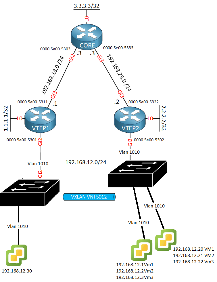
I have a question regarding the ARP broadcast flooding . When H1 send a Broadcast frame to VTEP1 with Destination MAC FF:FF:FF:FF:FF:FF . Then VTEP1 lookup the Vxlan Mapping table but there is no Mapping.So VTEP1 encapsulate the entire frame with VXLAN Hearder along with UDP and New IP header . The new IP header Dst IP will be Multicast IP because the VNI is associated with the multicast group . Now VTEP1 send the frame to CORE Router (Our RP) . My question is here …How VTEP2 will received packet from CORE .Why CORE Will flood this packet to VTEP2 ?
The mRouting table of Core :
CORE#show ip mroute 239.1.1.1
IP Multicast Routing Table

(*, 239.1.1.1), 00:00:49/00:02:45, RP 3.3.3.3, flags: B
  Bidir-Upstream: Null, RPF nbr 0.0.0.0
  **Outgoing interface list:**
**    GigabitEthernet3, Forward/Sparse, 00:00:44/00:02:45**
**    GigabitEthernet2, Forward/Sparse, 00:00:49/00:02:40**
What is the meaning of the Outgoing Interface list of mcast Routing table ?
Stay safe and healthy. Thx
BR//ZAMAN
Hello Zaman
Remember that the frame that reaches VTEP1 will be encapsulated. As far as that broadcast frame is concerned, it’s next hop will be H2. So once encapsulated, it is oblivious to the overlay network and mechanisms. All of the rules governing the transmission of the encapsulated frame from VTEP1 to the CORE to VTEP2 will involve the multicast mechanisms. So you can approach your question simply by looking at it as a purely multicast bidirectional PIM problem, since the overlay uses this technology.
You can take a look at the Multicast Bidirectional PIM lesson for more information too:
Remember that Multicast Bidirectional PIM allows traffic to flow up and down the shared tree, and each source is able to start sending whenever they want, since there is no register/register-stop mechanisms. So to answer your question, the CORE receives the multicast packet and will send it on to VTEP2 simply because VTEP2 is registered to the specific multicast group and has informed the CORE that it is interested in such traffic.
The outgoing interface list indicates the interfaces on the router out of which multicast traffic belonging to this group will be forwarded. So the very fact that Gi3 is in the list, indicates that VTEP2 is interested in this specific multicast group, and has informed the CORE of this. So any traffic arriving at the router with a multicast destination address of 239.1.1.1 will be forwarded out these interfaces.
I hope this has been helpful!
Laz
Hi Laz,
Thanks for your answer . Regarding Multicasting my understanding was whenever a host send a IGMP join message to Mcast Router then Router will send a PIM join message to RP to telling that I am interested for the multicast group and RP will send the packet accordingly .But here from the Configuration I didn’t see any PIM enable on host interface or host side .Thats the confusion .Thanks
BR//ZAMAN
Hello Zaman
Remember that the multicast configuration only exists in the underlay network. The actual hosts (H1 and H2) are oblivious to the multicast functionality or the infrastructure behind the VTEP routers. However, you are correct that the configuration is somewhat different as far as the hosts that join the the multicast group go.
Note that the mutlicast configuration is exactly the same as that shown in the Mutlicast Bidirectional PIM lesson, except for the configuration of the hosts receiving the multicast traffic. In this configuration, the hosts are actually the NVE interfaces on the VTEP1 and VTEP2 routers. Notice the last command on the NVE 1 interface of both routers:
VTEP1 & VTEP2
(config)#interface NVE 1
(config-if)#no shutdown
(config-if)#source-interface Loopback 0
(config-if)#member vni 5012 mcast-group 239.1.1.1
That last command is the counterpart of the ip igmp join-group 239.1.1.1 command in a normal multicast configuration. Otherwise, all the rest of the commands are the same. You can see the multicast routing being enabled, the ip pim sparse-mode command in the interfaces, as well as the configuration of the RP in all three routers. You can also see the command that enables bidirectional PIM .
I hope this has been helpful!
Laz
I ran into this kind of error:
VTEP2#show ip mroute 239.1.1.1
Group 239.1.1.1 not found

VTEP2#show ver
Cisco IOS XE Software, Version 16.03.03
Hello Dan
This error is not due to an unsupported feature, but probably due to a misconfiguration. The command is used to show the multicast routing table, and the groups that are registered within it. From the moment that you are getting a result where the specific group is not found, this indicates that it has not been configured initially. I suggest you issue the following command to see all the multicast routes in the device:
show ip mroute
If there are none, then you should go back and check your multicast configuration based on the lesson.
I hope this has been helpful!
Laz
Hi
Thanks for this great post.
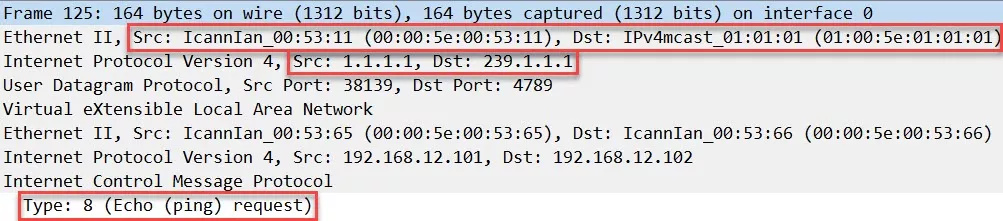
According to above trace, host1 alreasy knows MAC of host2 before VTEP MAC learning . Is it possible ?
Initially, host1 does not know host2 MAC. It sends ARP multicast. After host2 reply, both host1 and vtep learn host2 MAC at the same time. Could you please explain ?
Cloud topology is spine-leaf.
Without vxlan, spine forwards layer3 packet, leaf forwards layer2(vlan) frame. With vxlan, both spine and leaf forward layer3 packet(multicast, unicast). True or false ?
Thanks
Michael
Hello Michael
Remember that the hosts between them believe they are on the same subnet, connected to the same switch. Because they’ve already communicated with each other, they already know each other’s MAC addresses, through ARP packets that have already been exchanged. In the lesson, Rene cleared the bridge domain MAC table which resides on the VTEP devices. This has no effect on the ARP tables of the hosts.
So in the above Wireshark capture, you can see that for the “inside” or encapsulated ETHERNET and IP headers, all is normal. For the outside ETHERNET and IP headers, the first ICMP packet is multicast, the return ICMP packet is unicast, and the second ICMP packet is also unicast.
The answer here is “it depends”. This is because a spine and leaf architecture can function at L2 or L3. You can indeed configure such an architecture without VXLAN such that the spine does forward layer 3, and leaves are at Layer 2, but you are not restricted to such a configuration.
With VXLAN, the idea is that the overlay network can indeed be L2 at both spine and leaf, while the underlay network can be L3 at both spine and leaf, so really there is no restriction.
Are you speaking about a particular case of configuration? If so, please clarify so that we can answer more accurately.
I hope this has been helpful!
Laz
Hi Laz/Rene
-
Could you plz solve this for me?
If I change the topology to this, do we need to change the config at all?
I need to extend the vlan 1010 from the right switch to the left switch…
and what about trunks, VXLAN ports(service instance) doesn’t support trunks? so that we can tag the traffic from downstream on any VLAN and send it over the vxlan tunnel to another destination? in other word can Gi2 be a trunk port that goes to a switch?