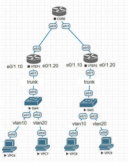
Yes that is correct. If you replace H1 and H2 with two switches, as you have done in your diagram, then those switches will simply need to be configured with access ports on VLAN 1010. No change in the config of VTEP1 and VTEP2 is necessary. From the moment the encapsulation untagged command is used on Gi2 of both VTEP1 and VTEP2, these ports can connect to hosts or to access ports of switches.
Yes, it is possible to make Gi2 on the VTEP devices function as a trunk. This is achieved using the encapsulation dot1q command in which you specify the VLAN(s) that will be tagged. For example:
encapsulation dot1q vlan 5-10,12
The above command specifies that VLANs 5, 6, 7, 8, 9, 10, and 12 are allowed on this port. Any switch connected to such a port should be configured as a trunk port with the same allowed VLANs. This is similar in concept to the router on a stick configuration.
How vxlan achieves 16 million when we have 1:1 mapping with vni to vlan ?
I have succeeded in mapping VLANs to vnis,
but I would like to know how can I use different vnis on access ports.
I have a question.
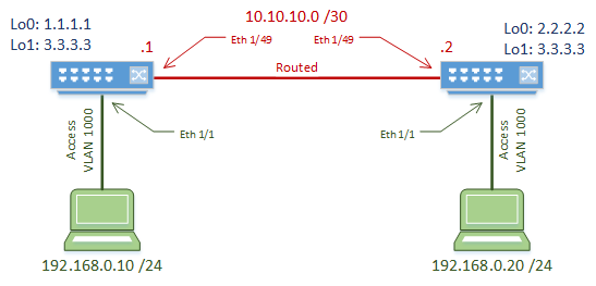
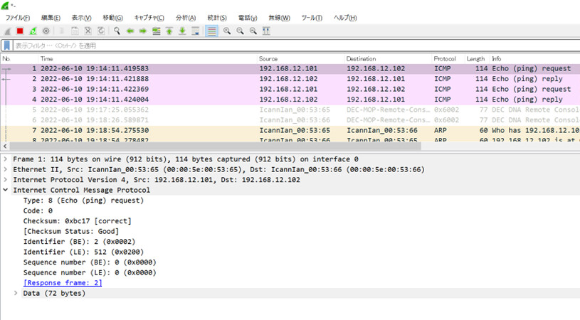
Part “Unknown Unicast Traffic”, ping to H2(192.168.12.102) form H1,
so I see Wireshark packet capture, the first ICMP request is not flooding.
Why? Missconfiguration?
H1#ping 192.168.12.102 repeat 2
Type escape sequence to abort.
Sending 2, 100-byte ICMP Echos to 192.168.12.102, timeout is 2 seconds:
!!
Success rate is 100 percent (2/2), round-trip min/avg/max = 3/3/3 ms
H1#
In the 2.3 Unknown Unicast Traffic section of the lesson, the first thing that Rene does is clear the bridge domain MAC table in both VTEP devices. This ensures that there are no MAC addresses present in the MAC address table, which will result in a multicast communication for the first echo request.
Also, you must make sure that the packet capture is being taken at the right place. If the packet capture is taking place at H1, then you will see a unicast communication, because the destination IP is known to H1. However, when this reaches VTEP1 and is sent on into the VXLAN fabric, it becomes a multicast communication. The proper location to take the packet capture is on the egress of Gi3 on VTEP1 or even at one of the interfaces on the CORE.
Thank you for your reply.
Oh, I was making a mistake! As you say, I wasn’t doing packet captures in the right place. After setting it to the Gi3 exit of VTEP1, it was the result I expected! Thank you so much!
I have everything working in gns3.
All the ospf, pings, multicast and vxlan verification commands show the expected output.
However i cannot ping between hosts. VTEP1#show bridge-domain 1 - this only shows the mac address of host 1 - same on VTEP2 - only shows host2 mac address. VTEP1#show nve interface nve1 detail - should show out / in packets - mine only shows outs. Same on vtep2.
I’m not great on multicasting - but as i’ve said all the verification commands do return the expected output.
Looks like the vtep is not forwarding on the traffic - evening though the underlay is working correctly. Anything else i should check ??? Or any type of logging i can turn on ?
Edit : I have no nve peers - the output is empty from # show nve peers
Edit 2 : I found the solution.
I resolved the above issue - in a roundabout way - when really it would have been easier to check my running config - my bad !!!
It turned out i did not have on the vtep nodes the loopback interface command : # ip pim sparse-mode
If you have a suggestion for a lesson or for content on the site, feel free to use the Member Ideas page below. You may find that others have suggested similar topics to what you’re looking for, and you can add your voice to theirs.
Notice the command encapsulation untagged. In the lesson, the interface accepted untagged frames. In your case, you want e0/1 of each VTEP to accept tagged frames, so you would have to configure dot1q encapsulation. Take a look at this context-sensitive help with the available options:
Creating such a topology of a VXLAN network with MP-BGP EVPN would be an interesting lesson to examine. I suggest you go to the following Member Ideas page of NetworkLessons and make your suggestion there as to a new lesson topic. You may find that others have suggested something similar, and you can add your voice to theirs.
In the meantime, here is some Cisco documentation that may be useful for you concerning VXLAN and MP-BGP EVPN:
How does inter-VNI routing take place in the flood and learn method?
Since VNI prefixes are not advertised in the underlay network, how are the VNI prefixes advertised to Spine switches as well as Core Switches for North-South traffic flow?
Inter-VNI routing in the flood and learn method is achieved through a default gateway. The VXLAN Tunnel Endpoints or VTEPs within the same VNI can communicate with each other directly. However, for communication between different VNIs, there needs to be a default gateway, which is typically a router or a Layer 3 switch. This gateway is responsible for routing traffic between different VNIs. It learns the MAC addresses of the hosts in each VNI just like a traditional switch does - by flooding the first packet of an unknown destination to all its ports and then learning the source MAC address of the return packet.
VNI prefixes are not advertised in the underlay network because the underlay network only needs to provide IP connectivity between VTEPs. The overlay network, which includes the VNIs, is decoupled from the underlay network. However, for North-South traffic flow, the VNI prefixes need to be advertised to the Spine and Core switches. This is typically done through an external routing protocol such as BGP. The border leaf switches, which connect to the Spine and Core switches, advertise the VNI prefixes to the Spine and Core switches using BGP. The Spine and Core switches then use this information to route traffic to the appropriate VNI.
Does that make sense? If you have any further questions, please let us know!
The majority of labs that are created on the NetworkLessons site (including this one) use either Cisco VIRL (for the older ones) or Cisco Modeling Labs (CML). This particular lab uses CML with CSR1000V routers running the following version:
Cisco IOS XE Software, Version 17.03.06
Cisco IOS Software [Amsterdam], Virtual XE Software (X86_64_LINUX_IOSD-UNIVERSALK9-M), Version 17.3.6, RELEASE SOFTWARE (fc2)
Now it’s not necessary to use the exact same setup to replicate the lab in an emulator. You can also use other emulators such as EVE-NG or GNS3. You can learn more about these options at this NetworkLessons note about how to practice labbing.
ok thank you i am a little confusing so vxlan can be deployed in ISR and Nexus in the same architecture spine and leaf?? and this technology is used for only data centers or what are the most usual case of use? thank you for the feedback