How to configure Static NAT on Cisco IOS Router

Hello Chris,

There is:

ip nat inside source:

  • Translates the source IP address of packets that travel from inside to outside.
  • Translates the destination IP address of packets that travel from outside to inside.

ip nat outside source:

  • Translates the source IP address of packets that travel from outside to inside.
  • Translates the destination IP address of packets that travel from inside to outside.

So in your first example: source IP address 192.168.12.1 is translated to 192.168.23.2 when it translates from inside to outside. Destination IP address 192.168.23.2 is translated to 192.168.12.1 when the packet travels from outside to inside.

In the second example, we translate source IP address 192.168.23.2 to 192.168.12.1 when the packet travels from the outside to the inside. We translate destination IP address 192.168.12.1 to 192.168.23.2 when the return packet travels from the inside to the outside.

This question comes up every now and then so I decided to create some examples for it:

https://networklessons.com/cisco/ccie-routing-switching/ip-nat-inside-source-vs-ip-nat-outside-source/

Hope this helps!

Rene

1 Like

Hello there,

just joined the community and already struggling with a lesson :slight_smile:
I cannot configure ip nat commands on a physical interface of a C3560 multilayer switch. I can configure it on a vlan interface but not e.g. on Gi0/1. The CLI just don´t recognize the ip nat inside command.
The lab is running in Packet Tracer 7.2.2.0418. Is that a limitation of the switch or the virtual environment?

Hello Andy

NAT can only be applied to a Layer 3 interface. That means that it can only be applied to a VLAN interface (SVI) or a physical interface for which the command no switchport has been applied. This command converts a physical interface from a layer 2 to a layer 3 interface. Once that is done, you will see that the ip nat commands are enabled.

I hope this has been helpful!

Laz

Hi Rene,

Can you let me know if we have configured one-to-one nat with route-map; Out-side server has initiated the traffic, will that check route-map for outbound traffic ?

Scenario

Clients  MPLS  FIS DC

Clients Real IP : 192.168.6.0/24
Clients NAT Range : 10.27.195.0 /24
FIS DC IP : 10.29.154.4
209.149.158.0 0.0.0.15
10.96.18.0 0.0.0.255
10.96.140.0 0.0.1.255
10.96.202.0 0.0.0.255
10.96.72.0 0.0.7.255
199.38.140.0 0.0.0.255
156.55.112.0 0.0.7.255
10.121.8.0 0.0.3.255
10.118.27.40 0.0.0.7
10.118.32.0 0.0.31.255
10.118.154.0 0.0.1.255
10.118.184.0 0.0.7.255

Situation 1 :- FIS DC is initiating Traffic
Situation 2 : Clients different Branch offices are initiating traffic

Configuration done on Client side (NOT ON FIS SIDE)

route-map FIS_TRAFFIC permit 10
match ip-address access-list 102
!
ip access-list extended 102
deny ip host 10.29.154.4 any
permit ip any 209.149.158.0 0.0.0.15 
permit ip any 10.96.18.0 0.0.0.255
permit ip any 10.96.140.0 0.0.1.255
permit ip any 10.96.202.0 0.0.0.255
permit ip any 10.96.72.0 0.0.7.255
permit ip any 199.38.140.0 0.0.0.255 
permit ip any 156.55.112.0 0.0.7.255 
permit ip any 10.121.8.0 0.0.3.255
permit ip any 10.118.27.40 0.0.0.7
permit ip any 10.118.32.0 0.0.31.255 
permit ip any 10.118.154.0 0.0.1.255
permit ip any 10.118.184.0 0.0.7.255
 !
permit ip 209.149.158.0 0.0.0.15 10.27.195.0
permit ip 192.168.6.0 209.149.158.0 0.0.0.15 
 !
ip nat inside source static network 192.168.6.0 10.27.195.0 /24 route-map FIS_TRAFFIC

Situation 1: IF FIS DC has initiated traffic, will that be checked Static NAT rule and route-map for outbound traffic and will do the translation or return traffic will be matching with static NAT Rule???

Hello Manami

When you configure NAT using route maps, what you are actually implementing is called Policy NAT. This allows you to create more specific NAT rules as you have done with your route maps. In this case, your NAT rule will translate from the inside network 192.168.6.0 to the outside network 10.27.195.0 /24 so any traffic originating from FIS (which from what I understand is outside) will not be translated, and will not be matched to the route map.

Take a look at this lesson for more information about policy NAT:

In order to allow outside hosts to reach inside devices, you will have to take a look at the following lesson:

I hope this has been helpful!

Laz

Hi,

When I’m learning NAT, i’m always confused with the correlation between NAT and routing. Would you please explain how would routing fits into NAT? The other question is if we would want to do a filter, how would we know whether we should choose the real IP or the mapped IP?

Thank you very much for your help,

Hello Helen

NAT involves the translation of source and/or destination IP addresses in the header of an IP packet as it traverses a NAT router. The NAT router simply changes the IP address in the header of the packet according to the configured NAT rules.

Now NAT and routing are two different operations, but when they are both occuring in a network, it can be confusing as to what the role of each is. To help us, let’s take a look at the following diagram:


Notice here that there is a PC connected to an internal enterprise network, which is connected to the NAT router. The NAT router is in turn, connected to the Internet. The PC wants to communicate with the Web Server. Now remember, that routing is applied based on the destination IP found in the header of the IP packet.

The PC will send a packet to the web server using the web server’s IP address as the destination IP. Routing will take place in the LAN based on the destination IP, and will thus be routed to the NAT router. The NAT router will translate the source IP address (that of the PC) to an public IP address. Note that the destination IP has not been changed. The NAT router sends the packet to the next hop router, through the internet, and is routed until it reaches the web server.

Notice that the destination IP did not change for the full extent of the journey from PC to web server. The source IP did change, due to NAT.

Now on the return trip, the destination IP address will be that of the NAT’ed address of the PC, that is, the public address to which the PC’s private address was translated. Routing within the Internet will bring that packet to the NAT router. Once it reaches the NAT router, this address is translated to the private address of the PC. Based on this new destination address, the routing continues as the NAT router sends it into the enterprise network, until it reaches the PC.

So you can see that the routing procedure takes place “on either side of the NAT router” and always uses the destination address of the IP packet. If that destination address doesn’t change (from PC to Server), the routing simply continues. If it does change (Server to PC), then the new destination address is used to continue the routing process.

This is an excellent question, and it depends upon what is known as NAT order of operations. When a packet comes into a NAT router, what is applied first? The translation? ACL filtering? routing? An excellent document that clearly states which operations are applied when for NAT is the following:

Here you can see for each direction (outside to inside, and visa versa) what takes place. For both directions, input access lists are applied before translation, while output access lists are applied after translation. Take a look at the document for more details.

I hope this has been helpful!

Laz

1 Like

Thank you very much Laz.

1 Like

Hi Rene/Laz,

Can you clarify if there is any limitation of NATing on opposite sides.

. All routers are connected using OPSF. I have 4 loopbacks on R3(1.1.1.X/32) and R4(2.2.2.X/32). I have implemented PAT on routers R1 and R2. The configs are as follows:

R1:

interface GigabitEthernet0/0
 ip address 192.168.1.1 255.255.255.248
 ip nat outside
 ip virtual-reassembly in
 duplex auto
 speed auto
 media-type rj45
interface GigabitEthernet0/1
 ip address 10.0.0.1 255.255.255.248
 ip nat inside
 ip virtual-reassembly in
 duplex auto
 speed auto
 media-type rj45

ip nat inside source list 10 interface GigabitEthernet0/0 overload
access-list 10 permit 10.0.0.0 0.0.0.7
access-list 10 permit 1.1.1.0 0.0.0.255
access-list 10 permit any

R2:

interface GigabitEthernet0/0
 ip address 192.168.1.2 255.255.255.248
 ip nat outside
 ip virtual-reassembly in
 duplex auto
 speed auto
 media-type rj45

interface GigabitEthernet0/1
 ip address 11.0.0.1 255.255.255.248
 ip nat inside
 ip virtual-reassembly in
 duplex auto
 speed auto
 media-type rj45
ip nat inside source list 10 interface GigabitEthernet0/0 overload
access-list 10 permit 11.0.0.0 0.0.0.7
access-list 10 permit 2.2.2.0 0.0.0.255
access-list 10 permit any

If I dont do PAT on one of the side it works just fine, up on PATing on both sides the R3 is not able ping R4 and vice versa. From my understanding if R3 tries to ping R4 the packet flow should be as follows:

R3: 1.1.1.1 (S) ping 2.2.2.2 (D)
R1: 1.1.1.1 -> 192.168.1.1(S) while exiting interface gi0/0 to 2.2.2.2 (D)
R2: 192.168.1.1(S) -> 2.2.2.2(D)
R4: 2.2.2.2(S) -> 192.168.1.1(D)
R2: 2.2.2.2->192.168.1.2(S) ->192.168.1.1(D)
R1: 192.168.1.2(S)-> 1.1.1.1(D)

I am assuming that R1 and R2 will be stateful while performing NAT or PAT although I am not really sure, but I think this is how they remember the different ports assigned to different internal ip’s.

Attaching Screen captures of debug messages.

Can you help me find where exactly am I doing wrong or where my understanding of NATing is not right. Thanks a ton in advance.

Hello Teja

The behaviour that you are describing makes sense. NAT, especially with the “overload” feature (PAT), is designed to enable many devices on the inside to communicate with devices on the outside. Unless special provisioning is implemented, this communication must be initiated by the hosts on the inside, and any return traffic will be allowed in, due to the stateful nature of NAT. That is, it detects that the return traffic is a response to the original request, and “allows” that traffic in. Any traffic that originates on the outside will not be allowed in, by default.

Let’s take a look at your topology:
image
Any traffic originating from R3 to R4 will be successfully NAT’ed at R1, will reach R2, and will be dropped. This is because, from the point of view of R2, this traffic originated on the outside. There is no stateful entry in the translation table that indicates that this is return traffic, so it is dropped. The same goes for traffic from R4 trying to reach R3, it will be dropped at R1, because it originated on the outside.

If you disable PAT on either R2 or R3, then the communication is successful, because there is no attempt for translation from outside to inside, but the packets are simply routed.

This example you shared highlights the difficulties involved in implementing end to end services between sites that run NAT on both ends. In order to successfully implement such communication, it is necessary to use features such as port forwarding.

I hope this has been helpful!

Laz

3 Likes

Thanks a lot Laz. Its clear now.

Hi Klaus,
When a ping is done from the NAT server to the Webserver there is a failure.

That happens because when the NAT server receives the Echo reply from the Webserver, it still thinks that the packet has to be translated and forwarded to 192.168.12.1

1 Like

I saw the lesson (pretty good, BTW), but I would like to share some additional troubleshoot commands that may facilitate people in this forum to get a better understanding.

Forwarding/NAT debug

Cisco by default offloads packet switching to the interface hardware always when possible (fast switching). So, if you run debug ip packet on the NAT router, you’ll not see anything because the debug occurs on the processor (CPU), not on the interface hardware. So, let’s disable fast switching on the proper interfaces:

NAT(config-if)#no ip route-cache

And enable debug:

NAT#debug ip packet

Not, let’s run a single ping (only 1, so output will be easier to read):

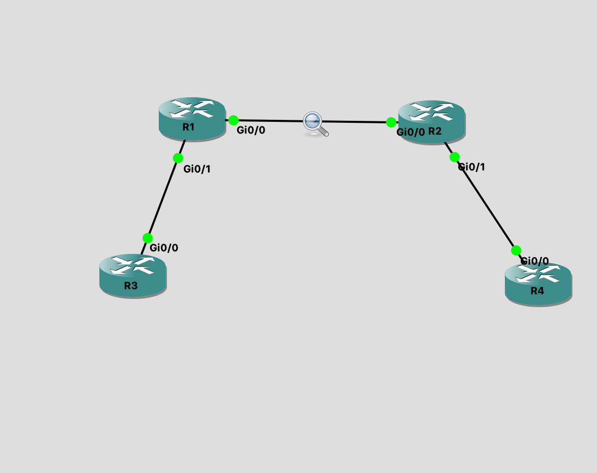
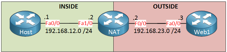
HOST#ping 192.168.23.3 repeat 1

In the NAT router, we’ll see:

*Jun 19 01:15:49.670: IP: s=192.168.12.1 (Ethernet0/0), d=192.168.23.3, len 100, input feature, Common Flow Table(5), rtype 0, forus FALSE, sendself FALSE, mtu 0, fwdchk FALSE
[...]
*Jun 19 01:15:49.670: IP: s=192.168.23.2 (Ethernet0/0), d=192.168.23.3 (Ethernet0/1), len 100, output feature, Post-routing NAT Outside(26), rtype 1, forus FALSE, sendself FALSE, mtu 0, fwdchk FALSE
[...]
*Jun 19 01:15:49.670: IP: s=192.168.23.2 (Ethernet0/0), d=192.168.23.3 (Ethernet0/1), g=192.168.23.3, len 100, forward
*Jun 19 01:15:49.670: IP: s=192.168.23.2 (Ethernet0/0), d=192.168.23.3 (Ethernet0/1), len 100, sending full packet

*Jun 19 01:15:49.671: IP: s=192.168.23.3 (Ethernet0/1), d=192.168.23.2, len 100, input feature, Common Flow Table(5), rtype 0, forus FALSE, sendself FALSE, mtu 0, fwdchk FALSE
[...]
*Jun 19 01:15:49.671: IP: s=192.168.23.3 (Ethernet0/1), d=192.168.12.1, len 100, input feature, NAT Outside(91), rtype 0, forus FALSE, sendself FALSE, mtu 0, fwdchk FALSE
[...]
*Jun 19 01:15:49.671: IP: s=192.168.23.3 (Ethernet0/1), d=192.168.12.1 (Ethernet0/0), g=192.168.12.1
NAT#, len 100, forward
*Jun 19 01:15:49.671: IP: s=192.168.23.3 (Ethernet0/1), d=192.168.12.1 (Ethernet0/0), len 100, sending full packet

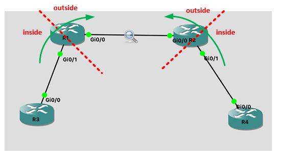
We can see the packet being received on Ethernet0/0 (in my particular case, equivalent to fastEthernet0/1 in the lesson) w/ source 192.168.12.1, being translated to 192.168.23.2 (phase output feature, Post-routing NAT Outside), and being forwarded to Ethernet0/1 (in my particular case, equivalent to fastEthernet0/0 in the lesson). Also, we see the packet being received in Ethernet0/1 w/ destination 192.168.23.2, the NAT being undone (destination changed back to 192.168.12.1 at phase input feature, NAT Outside), and then forwarded to Ethernet0/0.

Tips and tricks regarding debugging routing

You should be careful when doing such kind of debug in a real-world router, as (1) we’re disabling fast-switching and (2) we’re debugging all packets. This may result in big performance degradation.

I found some useful tips and tricks about how to properly debug in the following link: https://www.cisco.com/c/en/us/support/docs/dial-access/integrated-services-digital-networks-isdn-channel-associated-signaling-cas/10374-debug.html

Hello Rarylson

As always, thanks for your contribution!

Laz