I have a scenario,how do we achieve a redundancy between the core switch and our 2 SRX firewalls(HA active and Passive).We have a10GB connection from the GPON. we have vlans 23,24,25 that would dedicated for wireless network on the core switch
The goal is to achieve a redundancy link between core 9200 switch and firewall,currently all our route to the firewall is default.
my thoughts is to trunk the vlan23,24,25 to the primary firewall, or make an etherchannel to the firewall for this vlans,but my concern is how to achieve redundancy to the switch if the primary firewall fail,how would the the passive pick the vlans/etherchannel from the switch…
The redundancy here will be achieved by some mechanism that the firewalls have, and not by a feature of the switch. Briefly reviewing some related documentation, the SRX345 firewalls must be configured using what the manufacturer refers to as Redundant Ethernet interfaces (reths). From my understanding, these reths share the same IP address. If one firewall goes down, the other one will adopt the IP address and traffic (from the point of view of the switch and all devices behind it) continue to route traffic in exactly the same way. It seems to function similar to HSRP, where a virtual IP address is used.
I am not an expert in this particular type of firewall, but based on the documentation, I assume that the interfaces they provide to the switch are L3, so you couldn’t create a trunk or etherchannel between the switch and the firewalls.
I suggest you can create a VLAN with a /30 subnet between the 9200 switch and the two active firewalls, say VLAN 99. Connect the firewalls to access ports on VLAN 99 and make the SVI VLAN 99 the next-hop IP for traffic from the firewalls to your GPON network, and make the virtual IP address of the firewalls the next-hop IP for traffic from the switch to the networks behind the firewalls. That way, all your traffic in VLANs 23, 24, 25 and so on can reach the firewalls and beyond via interVLAN routing.
The failover mechanism would only exist within the firewalls and does not involve the configuration on the switch.
A broadcast packet that is received on an interface of a switch will be broadcast to all ports of that switch that are on the same VLAN. This is true for both an L2 and an L3 switch.
Both L2 and L3 switches are capable of creating multiple broadcast domains simply by creating multiple VLANs. Each VLAN will contain the broadcast within in. The difference is that an L3 switch is capable of performing routing between those VLANs while an L2 switch cannot, and requires an external router to do so.
If you’re talking about the first diagram in the lesson, then if you have more than one device on the cloud or the WAN, then each connection will be contained within its own broadcast domain. Remember that a router represents a boundary to the broadcast domain.
To read further about broadcast domains and how they are defined, take a look at the following lesson:
Also, to see how inter-VLAN routing takes place within an L3 switch, take a look at:
Hey,
If 2 pc’s which are behind 2 different switch configured access vlan 50 on the ports connected to the end devices (pc), can i configure the link betweeen the 2 switches as access or i have to configure the link as a trunk.
I know if both pc were configured on the native vlan (vlan 1), thus i can configure the link between the switches as access but i am not sure what happens when both sides configure in the same vlan but not the native vlan.
You can configure the link between the two switches as an access link that is on VLAN 50. Links between switches can be configured as access links or trunk links. If you only need to send a single VLAN over that link, it’s perfectly OK to use an access link.
However, in most cases where you have managed switches with multiple VLANs, you will usually create trunk links simply because you need to send more than one VLAN between switches.
@lagapidis
“A VLAN tag will only be added to a frame when it is exiting a trunk port. The VLAN tag will then be stripped when it enters the trunk port on the other end. So a VLAN tag will only exist on the frame while the fame is on the physical trunk link.”
This above statement still confuses me a bit. Can you please show this with a simple diagram, that exactly at which point a tag is added & where it is stripped?
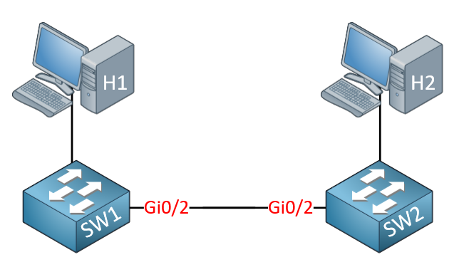
VLANs within switches are clearly separated by assigning specific VLANs to access ports. The only place you configure VLAN tagging is on trunks, where frames of multiple VLANs coexist. Therefore it is only on the trunks themselves that frames are tagged on. Imagine the following topology:
The connection between the switches is a trunk, while both hosts are on VLAN 10.
When H1 sends traffic to H2, the frame that exits H1 is untagged.
It enters the access port on SW1 which is assigned to VLAN 10. No tag is added yet.
It exits Gi0/2 of SW1 which is configured as a trunk. As it exits, a VLAN tag of 10 is added to the frame.
The frame enters Gi0/2. Gi0/2 reads the tag, sees it belongs to VLAN 10, removes the tag, and sends it to be switched to some host on VLAN 10.
Based on the MAC address table and the destination MAC address, it is switched to the port connected to H2.
H2 receives the frame and processes it.
So you can see that the frame exists with a tag only from the time it exits SW1 Gi0/2 until it enters Gi0/2 of SW3. If the frame traverses another trunk in its journey, it will be tagged again, and the tag will be removed again in the same way.
Hello team
I’m a little stuck on a configuration, please help me
How to use the same interface in two different VLANs.
I have two interfaces in Gi1 / 0/41 and Gi1 / 0/45 access on which the traffic arrives via the proxim antenna
I specify that its interfaces are in the Vlan1, the native Vlan.
So I want to use its interfaces in a new Vlan400 just to pass traffic
without messing around with the Users in the Vlan1.
Ports on a switch can be either access ports or trunk ports. Access ports can only have one VLAN assigned to them. Trunk ports on the other hand can be assigned multiple VLANs. When traffic is sent over a trunk port, an additional tag is added that specifies on which VLAN the frame belongs. If there is no tag, it is automatically placed on the native VLAN.
But remember, whenever you configure a port as a trunk port, the other end of that link must also be appropriately configured with the same allowed VLANs and native VLAN for it to function.
You can find out more about how to configure trunk ports here:
i always see labs about Vlans from a L2 switch to a router and a layer 2 switch to a layer 3 switch. But what if i got a more divergent environment of multiple layer 2 switches, multipple layer 3 and a router, all with vlans. How should get that fixed ? How do i connect the layer 2 switches to the layer 3 and the layer 3 to the router? I cannot use router on a stick i think. Thanks in advance.
It really depends on what you want to achieve. If you have multiple Layer 2 switches in your topology, and each Layer 2 switch contains multiple VLANs, then in order for there to be communication between the VLANs, you must get traffic to reach a device that performs routing. If this is a router, then you will have to configure router on a stick. If this is a Layer 3 switch, then you will have to connect the L2 and L3 switches via a trunk, and perform routing at the SVI of the L3 switch. You can find out more about that in the Inter-VLAN routing lesson.
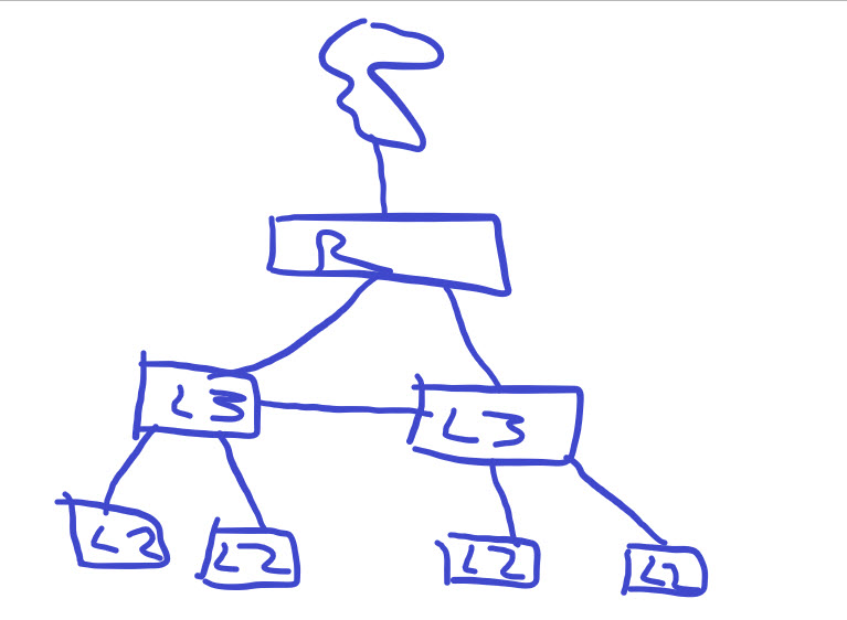
Many thanks for the reply. Lets sat i have got something like this in my example. Is this even possible? can it be done? Wil it bedone? I think i need to create trunks from the l2 to the l3 switches, but how do i get the routing fixed? Wil it be on the router trhough ROAS or ?
This topology can definitely be deployed without any problems. If you have more than one VLAN on each L2 switch, then you must have trunks between the L2 and L3 switches, so that any traffic that goes from one VLAN to the other will be sent to the L3 switch for routing and sent back to the L2 switch on the other VLAN.
So in this topology, you can configure the L3 switches to perform all of the routing between the VLANs that are configured on all the L2 switches. This can be done using InterVLAN routing. You can then arrange to have all traffic destined to the Internet (I assume your link above is to the Internet) go to the router for routing out of the local enterprise network.
In this case, you do not need to employ router on a stick. The links between the L3 switches and the router can be access ports with a configured SVI, or routed ports. In order to use SVIs for routing, take a look at this lesson:
The L3 switches will automatically be able to route traffic between the VLANs configured on them, assuming you have created an SVI for each VLAN. This is achieved using inter-VLAN routing. In order to be able to route traffic to the router and beyond, as well as from the router to the L3 switches, you will need to employ a routing protocol (like OSPF for example) or configure static routing. You can find out more about these concepts at the following lessons:
What is PVID? I am actually confused between PVID and sending untagged frames at egress node. I know that PVID is port VLAN ID but I don’t find why we use it and how is it different?
As you mention in your post, the Port VLAN Identifier or PVID is just another name for the VLAN ID or the VLAN tags used in Ethernet frames. Sometimes this terminology is used. You will find it most often in Cisco’s small business switches. This is because these switches originated from Linksys where were later incorporated into Cisco, but they retained much of the configuration parameters and terminology. It can get confusing if you’ve originally learned about VLAN tags from purely Cisco devices.
It’s not actually different from the VLAN tag, but it is applied somewhat differently within the switches’ configuration interface. It’s a matter of getting used to, and of understanding the philosophy. Reading some config examples will be helpful.
If you have a particular scenario in mind, you can share it with us so that we can further help you in understanding.
Hi, I have a question, not sure where to post it, but it is vlan related
lets say we have 2 vlans 10 and 20
a host that is on vlan 10 was configured(trunked) with 192.168.10.128/25 ( but also on this link to the host there is vlan 20 configured(trunked) as well, but not in use on the host)
another host that is on vlan 20 configured(trunked) 192.168.10.190/26
how would it act in a network, would it cause any issues ?
as we can all see that vlan 10 also falls into vlan 20 subnet.