I intentionally didn’t add the df-bit because I was investigating from a layer 2 perspective.
But I had tested that part before, and the df-bit did cause it to fail because the ip mtu was also set to 1400 on R2’s interface. As a consequence the response did not make it when I pinged above 1400 because it wasn’t allowed to fragment. So that part works as expected.
I just set up the following topology:
R1-------SW1--------R2
SW1 being L2 only, so IP fragmentation doesn’t come into it. I then set SW1’s interface connecting to R1 to an mtu of 1400:
SW1:
SW1#sh int Gi0/0 | i MTU
MTU 1400 bytes, BW 1000000 Kbit/sec, DLY 10 usec,
R1:
R1#sh ip int Gi0/0 | i MTU
MTU is 1500 bytes
R1#sh int Gi0/0 | i MTU
MTU 1500 bytes, BW 1000000 Kbit/sec, DLY 10 usec,
R2:
R2#sh ip int Gi0/0 | i MTU
MTU is 1500 bytes
R2#sh int Gi0/0 | i MTU
MTU 1500 bytes, BW 1000000 Kbit/sec, DLY 10 usec,
When I ping from R1 to R2:
R1#ping 155.1.12.2 size 1410
Type escape sequence to abort.
Sending 5, 1410-byte ICMP Echos to 155.1.12.2, timeout is 2 seconds:
!!!
Success rate is 100 percent (5/5), round-trip min/avg/max = 3/3/4 ms
R1#ping 155.1.12.2 size 1411
Type escape sequence to abort.
Sending 5, 1411-byte ICMP Echos to 155.1.12.2, timeout is 2 seconds:
…
Success rate is 0 percent (0/5)
The switch gives the same result the as routers, it allows up to 1424.
I’m wondering if this is because it is allowing for a header size that could potentially be 24 bytes, rather than the usual 14, hence the extra 10.
Thanks for the details. This is an interesting one. I recreated the topology you suggest and I have been able to replicate your results. But it’s not immediately perceivable why we get this behavior. So let’s think this through.
When you ping using a size of 1400, what you capture using Wireshark is a frame size on the wire of 1414. So the actual Layer 3 PDU, including IP and ICMP headers is 1400, and the header of the Ethernet frame is 14 for a total of 1414 egressing the host.
Those 1414 bytes of frame reach the interface of the switch, which is set up to have an interface MTU of 1400. But it allows a frame of size up to 1424 on the wire to enter. So the Interface MTU must omit some of the headers of a total size of 24 bytes. Let’s examine what headers are added to an ICMP ping.
Looking at a Wireshark capture of a ping of size 1410, I see the following:
ICMP payload: 1382 bytes
ICMP header 8 bytes
IP header 20 bytes
Ethernet header 14 bytes
All of that equals 1424 bytes. So when H1 pings a size of 1410 bytes, it’s really 1382+8+20 = 1410. Plus the 14 bytes of the Ethernet makes it 1424 on the wire.
Now when the switch’s interface with an MTU of 1400 receives this, somehow, it does not consider 10 extra bytes as part of that MTU, and lets them through… To be honest, I don’t know. I’ll have to think about this some more, and share it with Rene to see if we can shed some light on it. Thanks for your patience.
Thanks for investigating. I assumed it was either:
A bug in CML (which you will have disproved if you are using physical H/W)
or
As the MTU configured on the interface is for the frame payload and not its entire length, maybe the switch adds the maximum header size possible and performs the size check on the entire frame (not just the payload) when it is received. This means it allows for headers up to 24 bytes in size, not 14, and I’m taking up the extra 10 bytes with more payload. Just a theory.
I only stumbled across this because I was trying to break OSPF adjacency formation by dropping the MTU to a size that allowed hello packets to pass but nothing else but it wasn’t behaving as I expected.
After further investigation, there are a couple of interesting things involved with this scenario. The lab you created, and the one I created as well, were both on CML, so we created the exact same scenario. The first interesting thing is that on physical hardware, it’s not possible to reduce the L2 MTU per interface to a value of less than 1500 bytes. Indeed on most IOS platforms, you can only apply the system MTU globally, and with a minimum of 1500. Even on some physical platforms where you can configure MTU per interface, it’s still a minimum of 1500.
Secondly, Rene tested this out on real hardware (WS-C3850-48T), and with an MTU size of 1500, was able to ping up to a size of 1504 but not 1505:
Success rate is 100 percent (1/1), round-trip min/avg/max = 1/1/1 ms
R1#ping 192.168.12.2 size 1504 repeat 1
Type escape sequence to abort.
Sending 1, 1504-byte ICMP Echos to 192.168.12.2, timeout is 2 seconds:
!

Success rate is 100 percent (1/1), round-trip min/avg/max = 1/1/1 ms
R1#ping 192.168.12.2 size 1505 repeat 1
Type escape sequence to abort.
Sending 1, 1505-byte ICMP Echos to 192.168.12.2, timeout is 2 seconds:
.
On the wire, the frame length is 1518 bytes. This is expected behavior because it allows for an additional 14 bytes for the Ethernet header and another 4 bytes for a possible VLAN tag. He tried it again with an MTU of 1600, and a ping of 1604 went through but not 1605.
So it seems to be an issue with the emulator. I’m curious to find out what would happen in a similar topology in GNS3 or EVE-NG.
Hmm, that’s interesting. It seems that the emulated topologies and environments share this strange calculation of the MTU. In any case, thanks for sharing that, it’s good to keep in mind.
About Path MTU Discovery. If the client notices that its 1500-byte packet was dropped because the MTU was lowered somewhere to 1476 (or just a lower value), what exactly will it do with the 1500-byte data? It won’t fragment them, right? Will it just break the packet down into smaller pieces, or? But that’s fragmentation, isn’t it? And that’s undesired.
Or is it safe to say that fragmentation or reassembly is okay on the hosts as they have time to do all that but not on a networking device like a router whose job is to forward packets as fast as possible?
Also, when a packet fragment is dropped, why do we retransmit the entire packet and not just the fragment?
Hi Rene, but i can see in this lesson you stated that it includes Ethernet header. I was in good understanding till i reach this Q&A - 47, now i am confused. Could you please brief me on this.
The Layer 2 MTU doesn’t include the Ethernet header. The MTU that is configured on an L2 interface of a switch, refers only to the payload of the Ethernet frame.
At Layer 3, the IP MTU includes the IP header and the TCP header as well.
So it makes sense that, as defined above, the L2 MTU is equal to the L3 MTU. If we imagine the Ethernet frame, the IP packet, and the TCP segment as boxes that fit into one another, we can think about MTU measurements as follows:
The L2 MTU is measured as the capacity of the box that will encapsulate the upper layer packet. It’s a measurement of the INSIDE of the box, in other words, the size of the payload it can carry, without measuring the actual dimensions of the box itself. So we leave out the box itself which is the additional 14 bytes.
The L3 MTU is measured as the size of the OUTSIDE of the box at the IP layer, that is, the IP payload AND the header. It includes the dimensions of the box, so it has a value of 1500 which comes from the 1480 for the payload and 20 for the IP header.
The TCP MSS is measured as the INSIDE of the TCP box, so it doesn’t include the TCP header. That means it must be the IP MTU - IP header - TCP header which is 1500-20-20=1460.
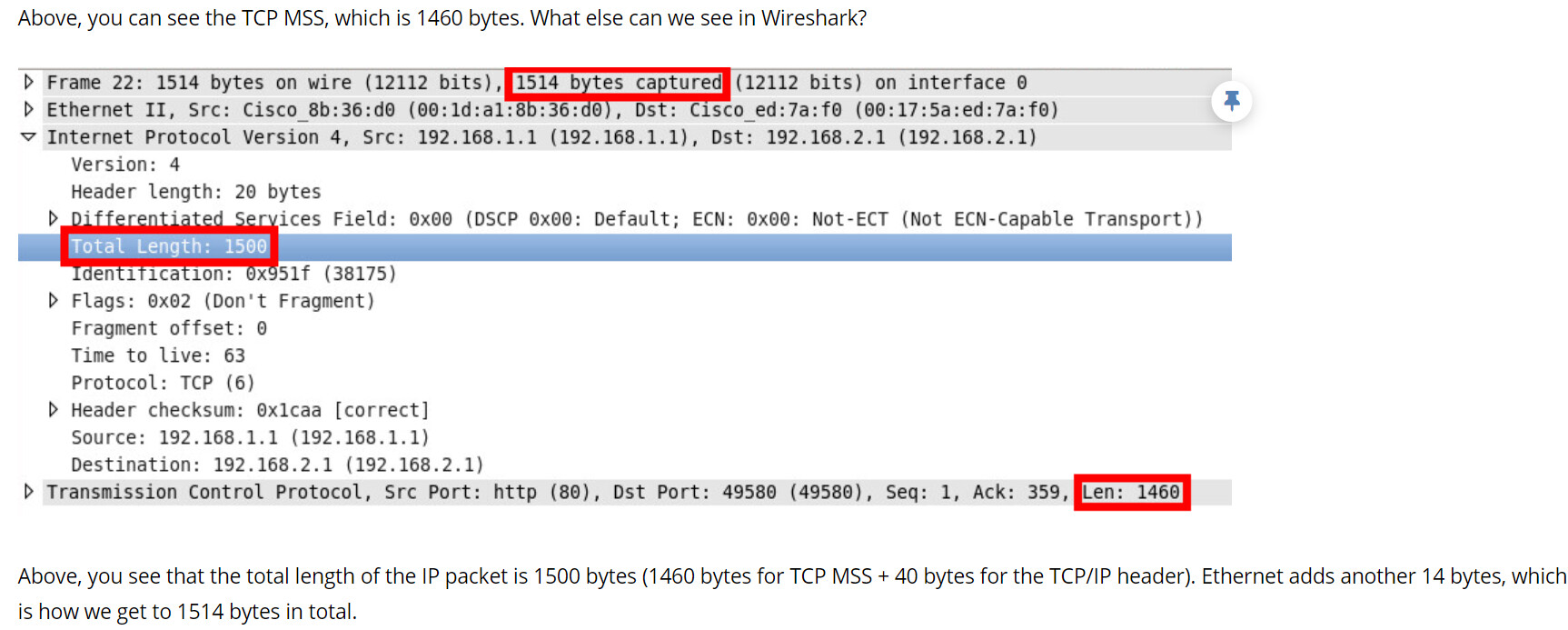
So in the lesson, you can see the following measurements in the packet capture:
The size of the Ethernet frame including the “box” is 1514, but the MTU at this layer is defined without the box, so it is 1500.
The size of the IP packet including the “box” is 1500, and the MTU at this layer is defined with the box, so that is also 1500. But the inside size of the box when we remove the 20 bytes of the IP header is 1500-20 = 1480. That’s the maximum size of the TCP segment with its header that it can accommodate.
The size of the TCP MSS doesn’t include its “box”, so that’s 1480 - 20 =1460.
So that’s how you get the numbers in the packet capture. And the statements in Rene’s post remain true. Does that make sense?
If a client is informed via PMTUD mechanisms that its 1500-byte packet was dropped due to a lower MTU, it will indeed need to break the packet into smaller pieces.
However, it’s essential to differentiate between fragmentation at the IP layer, which is generally undesirable, and fragmentation at the transport layer (like TCP), which is more acceptable. When we talk about avoiding fragmentation, we’re usually referring to IP fragmentation. This is because IP fragmentation can cause performance issues and security vulnerabilities.
On the other hand, TCP can segment the data into smaller chunks before sending it to IP. If the TCP layer knows the Path MTU, it can send segments of the appropriate size to avoid IP fragmentation. This process is referred to as “segmentation” rather than “fragmentation” to differentiate it from IP fragmentation.
PMTUD determines the largest packet size that can be sent without fragmentation, which in turn, directly sets the MSS, which is the largest segment of data that can be sent in a single TCP packet, thus avoiding fragmentation at lower layers..
Regarding your question about retransmitting the entire packet instead of just the fragment, the reason is that IP fragmentation and reassembly is a complex process that can be prone to errors. If a single fragment is lost, the entire packet cannot be reassembled and must be retransmitted. It’s also worth noting that the receiver may not know that a fragment is missing until it tries to reassemble the packet, which could introduce additional delay.
Hello Lazarus,
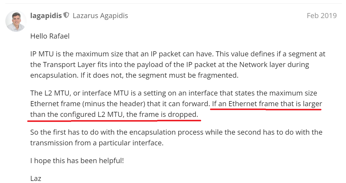
you stated in this post the “If an Ethernet frame that is larger than the configured L2MTU then the frame is dropped”. Are you referring the frame with Eth overhead. its bit confusing now.
if i am not wrong, if IP MTU is larger than L2MTU then it will be dropped , right until DF is not set?.
Yes, let me clarify. This depends upon what process we are actually looking at.
When we talk about ingress traffic, if a frame larger than 1500 bytes (payload only, this does not include the Ethernet header) arrives on a port that has the L2 MTU set to 1500, then the frame will be dropped. It doesn’t matter what is found in the IP header DF bit. That is never examined for incoming traffic since the frame is never received or processed.
For egress traffic, if the traffic is being forwarded on a Layer 2 switch (that is, no decapsulation takes place up to Layer 3), then the frame will enter the switch from some port, and will attempt to be egressed out of another port. If the egress port has an L2 MTU of 1500 and the frame is larger than 1500 (again, payload only), then the frame will be dropped. This can happen if you have one port with a larger L2 MTU where those frames can enter the switch. Once they try to exit from a port with an L2 MTU of 1500 they are dropped. Again, if the switch is L2 only, then the DF bit of IP is not checked.
Now if we’re talking about a L3 switch, which is performing routing with SVIs, then we have decapsulation up to Layer 3, then here the DF bit is taken into account. This is examined during encapsulation from Layer 3 (IP) to Layer 2 (Ethernet). If the egress port has a L2 MTU of 1500, and the IP packet (including header) is larger than 1500 bytes, then the DF bit will be checked. If it is not set, the packet will be separated into two and put into two different frames to ensure that the MTU size is smaller than the L2 MTU of the exit interface. Does that make sense?
Hello Lazarus, Great explanation. Thank you. I have some doubts here. How is the TCP layer to be notified about the largest path MTU in the transit path, which could reduce the MSS to avoid IP fragmentation?. What kind of intelligence works here on notifying things to Layer 4?
Note: I understand both what MTU and MSS do so I am not asking about their function here. I understand that when a TCP connection is being established, the MSS is exchanged and it dictates the maximum size of the segment (without TCP and other headers) that one device can send to another.
I also understand that devices have MTU (which works on both layer 2 and layer 3) but for simplicity, it’s the maximum size of the packet (ethernet payload) that can be sent or received over a wire.
My question is, why do we need both? More specifically, why can’t we just rely on our MTU to ensure that we’re not sending packets that are too large? There’s also PMTUD (Path MTU Discovery) which allows the devices to discover whether there are any lowered MTU values along the path.
If there are, the ICMP Fragmentation Needed message is sent by the device and the receiving device sends smaller packets to accomodate for the lower MTU in the path.
So what’s the significance of MSS, then? Why can’t we use and rely just the MTU? Why do we need both?
If PMTUD is not being used, then TCP will typically negotiate an MSS value during the 3 way handshake based on other factors. More about that can be found below:
This is a good question, and the answer helps us to further understand the layered approach to networking that the OSI model gives us.
As you know, the interface MTU tells Ethernet the maximum size of the payload it can handle on a particular interface. The IP MTU tells a device the maximum size that an IP packet can have (including the header). This in turn will define the MSS at the Transport Layer.
You see, you must have mechanisms at each layer that deal with and manage the size of the segmentation/fragmentation. At the Transport layer, that’s the MSS. The IP MTU and the interface MTU only have meaning at their respective layers. They have no meaning for the Transport layer, because of the abstraction that takes place between layers.
Now there are cases where information from one layer must be conveyed to another layer in order for it to function correctly. For example, the IP header includes a protocol field that specifies the protocol is used in its payload (i.e. ICMP, OSP, GRE, TCP, UDP etc).
Similarly, using mechanisms such as PMTUD, information is passed from one layer to the other. As the interface and IP MTU info is passed to the transport layer, it must be converted to information this layer can understand, and that is the MSS itself. Does that make sense?
We have an access layer switch in our network, the default MTU is seen as 1500 and when we check the interface and the statistics, we see
“Dropped- frames” and “Paused-frames” more numbers in the access ports where the end devices are connected. Is this the normal behavior or need to look into this.
How do we overcome this issue.
If you are seeing dropped frames as well as pause frames on an interface, the problem that you are facing is probably not an issue with MTU. It sounds more like congestion.
Specifically, the pause frames seem to indicate congestion. Pause frames are a type of Ethernet control frame used in full-duplex Ethernet networks. They are sent by a network device to temporarily stop the transmission of data from another device. The primary purpose of these frames is to manage network congestion and avoid packet loss.
If you are seeing many pause frames along with dropped frames in the show interface counters, then I would start troubleshooting congestion issues.
If you’re still concerned about the MTU, I suggest you try using the ping command with a sweep range of sizes to see if there is an MTU issue. You can find out more about how to do that at this NetworkLessons note on the topic.
If it’s not the MTU, start investigating your traffic patterns, especially at the interface in question. Is it consistently at utilization of close to 100%? Check that out and let us know your results so that we can help you further.
Q1/If i have networks with 9000 mtu in all paths, and same for the servers which are connected with this network, if I capture the packets coming from the servers, will i see the mss 1460? Or 8960 with padding?
I meant, who is define the actual packet size and mss size regardless of the mtu path (let’s assume it is 9000 in all the path).
As far as i know some vendors calculate the mss by mss=mtu-ip-tcp=9860 (here if my payload below 9860, padding will take place to cover the required size which us 9860
Some others set the lower adjustment size which is 1460
Am i right?
Can you explain this plz?
——-
Q2/if the answer is 1460 in all cases (without manual adjustments) , why we need 9000 mtu in our networks? If the packet in all cases with all headers maybe not pass 1600?
The MSS is defined during the TCP handshake process. The MSS is usually calculated by taking the MTU and subtracting the IP and TCP header sizes. However, this value can be changed by the sender and receiver during the handshake. If all of your servers and network paths have a MTU of 9000, then the MSS can be up to 9000 minus the IP and TCP header sizes (40 bytes for IPv4), which is 8960. But this is only if the sender and receiver agree to use this MSS.
The actual packet size can vary and doesn’t necessarily have to be the MSS. The MSS is just the maximum size of the TCP payload, and the MTU in turn defines the maximum size of the MSS. If a packet’s payload is less than the MSS, then there won’t be any padding to make up the difference. The packet will simply be smaller.
You can think of the MTU on the network as the size of the pipes used in a city’s sewage system. The maximum width of the pipes may be set, but you don’t always use the full capacity of the sewage system network. In the same way, the MTU on the network may be 9000, but the sender and receiver may choose a smaller MSS for various reasons, including vendor-specific rules (for compatibility or other reasons), detected network congestion, or configuration parameters on the applications being used. And even then, each packet sent may be smaller than the MSS depending on the needs of the application and network services being served.
I kind of answered this already, but I’ll elaborate here. The reason for having a larger MTU like 9000 (also known as jumbo frames) is to increase the efficiency of data transfer. By increasing the amount of data that can be transferred in a single packet, you reduce the overhead of the IP and TCP headers on a per-byte basis. So by giving devices the option of using up to 9000 bytes MTU, any devices that take advantage of it will enjoy more efficient CPU usage and lower latency. However, all devices in the network path must support the larger MTU, or else fragmentation will occur, which can decrease performance.
Even though the packet with all headers might not surpass 1600 bytes, having the ability to send larger packets when needed can improve overall network performance.